
Loading article…
.jpg/500px-thumbnail.jpg)


ディーゼル機関車は、動力源がディーゼルエンジンである鉄道 機関車の一種です。いくつかの種類のディーゼル機関車が開発されており、主に機械的動力を駆動輪に伝達する方法が異なります。最も一般的なのは、ディーゼル電気機関車とディーゼル油圧機関車です。
初期の内燃機関車や貨車は、灯油とガソリンを燃料として使用していました。ルドルフ・ディーゼルは1898年に最初の圧縮点火エンジン[2]の特許を取得し、ディーゼルエンジンの設計は着実に改善され、エンジンの物理的サイズが縮小され、出力重量比が向上し、機関車に搭載できるようになりました。内燃機関は限られた出力帯域内でのみ効率的に動作し、低出力のガソリンエンジンは機械式トランスミッションと組み合わせることができますが、より強力なディーゼルエンジンには新しい形式のトランスミッションの開発が必要でした。[3] [4] [5] [6] [7]これは、これらの出力レベルではクラッチが非常に大きくなる必要があり、標準的な2.5メートル(8フィート2インチ)幅の機関車フレームに収まらなかったり、摩耗が早すぎて役に立たなかったりするためです。
最初に成功したディーゼルエンジンはディーゼル電気トランスミッションを使用し、1925年までに少数の600馬力(450kW)のディーゼル機関車が米国で運行されていました。1930年に、英国のアームストロング・ホイットワースは、スルザー設計のエンジンを搭載した1,200馬力(890kW)の機関車2台をアルゼンチンのブエノスアイレスグレートサザン鉄道に納入しました。 1933年、マイバッハが開発したディーゼル電気技術が、高速都市間2両編成のDRGクラスSVT 877の推進に使用され、1935年からドイツで他の流線型車両とともに量産に入った。米国では、主に1920年代後半にさかのぼるゼネラルモーターズの研究開発の取り組みと、バッド社による軽量車体設計の進歩により、 1934年後半にディーゼル電気推進が高速幹線旅客サービスに導入された。
第二次世界大戦後の経済復興により、多くの国でディーゼル機関車の普及が加速した。ディーゼル機関車は蒸気機関車よりも柔軟性と性能に優れ、運転・保守コストも大幅に低かった。[8]
歴史
鉄道利用への適応


鉄道機関車に内燃機関が使用された最も古い記録は、ウィリアム・デント・プリーストマンが設計したプロトタイプである。これは1888年に初代ケルビン男爵ウィリアム・トムソンによって検査され、「石油エンジンを機関車に応用した例を示すために、一時的な線路で稼働する台車に搭載されたプリーストマン石油エンジン」と説明された。 [9] [10] 1894年には、プリーストマン・ブラザーズによって製造された20馬力(15kW)の2軸機械がハル・ドックで使用された。[11] [12] 1896年には、ハーバート・アクロイド・スチュアートが設計したエンジンを使用して、イギリスのウーリッジにある王立兵器廠向けに石油エンジンの鉄道機関車が製造された。[13]これは熱球エンジン(セミディーゼルとも呼ばれる) を使用していたためディーゼルではありませんでしたが、ディーゼルの前身となりました。
ルドルフ・ディーゼルは、 1893年の著書「合理的な熱モーターの理論と構成」の中で、このエンジンを機関車の動力として使うことを考えていた。[ 14 ]しかし、初期のディーゼルエンジンはサイズが大きく、出力重量比が悪かったため、陸上車両の推進には不向きだった。そのため、当初は鉄道の原動機としてのこのエンジンの可能性は認識されていなかった。[15]研究開発によってエンジンのサイズと重量が削減されるにつれて、この状況は変わった。
1906年、ルドルフ・ディーゼル、アドルフ・クローゼ、蒸気・ディーゼルエンジン製造会社のゲブリューダー・スルツァーは、ディーゼル機関車を製造するためにディーゼル・スルツァー・クローゼ社を設立した。スルツァーは1898年からディーゼルエンジンを製造していた。プロイセン国鉄は1909年に同社にディーゼル機関車を発注し、スイスのヴィンタートゥールとロマンスホルンの間で試験走行を行った後、ディーゼル機械式機関車は1912年9月にベルリンに納品された。世界初のディーゼル機関車は1912年夏にヴィンタートゥールから同じ路線で運行されたが、商業的には成功しなかった。[16] 1913年の試験走行中にいくつかの問題が見つかった。 1914年に第一次世界大戦が勃発したため、それ以上の試験は行われなかった。機関車の重量は95トン、出力は883kW(1,184馬力)、最高速度は100km/h(62mph)であった。[17]
1920 年代半ばまでに、いくつかの国で少数の試作ディーゼル機関車が製造されました。
アジアの初期のディーゼル機関車と鉄道車両
中国
中国で最初に国産化されたディーゼル車両の一つは、 1958年に四方CSRが製造した東風DMU(東風)である。中国初のディーゼル機関車クラスであるDFH1の量産は、1959年の試作機の製作に続き、1964年に開始された。
インド
日本
日本では、1920年代からガソリン電気式鉄道車両がいくつか製造されました。日本の鉄道における最初の電気ディーゼル牽引車両と最初の空気流車両は、キハ43000クラスの2台のDMU3でした。[18]日本の最初のディーゼル機関車シリーズは、1950年から開発され、1953年から運用されたDD50クラス(国鉄DD50形)の双子機関車でした。 [19]
ヨーロッパの初期のディーゼル機関車と鉄道車両
最初の実用的なディーゼル車
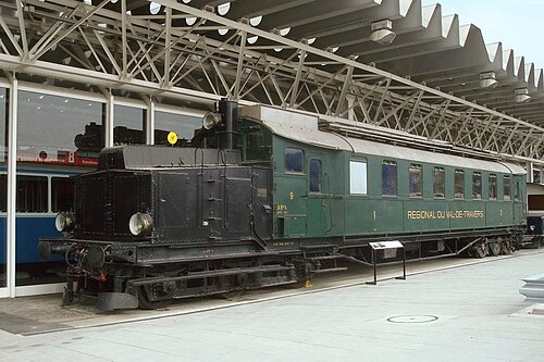
1914年、世界初の実用的な電気式ディーゼル車両が、ブラウン・ボベリ社の電気機器とスイスのスルツァー社のディーゼルエンジンを搭載して、ケーニヒ=ザクセン州鉄道向けにワゴンファブリク・ラシュタット社によって製造された。これらはDET 1およびDET 2に分類された(de.wiki [de])。第一次世界大戦中のガソリン製品不足のため、ドイツ国内では定期運行には使用されなかった。1922年に、これらはスイスのヴァル=ド=トラヴェール地方鉄道会社に売却され、1944年の路線電化まで定期運行に使用された。その後、同社は1965年までこれらをブースターとして運用した。
フィアットは1922年にイタリア初のディーゼル電気機関車を製造したと主張しているが、詳細はほとんど不明である。フィアット-TIBB Bo'Bo'ディーゼル機関車が950 mm(3フィート 1インチ)の鉄道用に数台製造された。+1924年から1925年にかけての試験を経て、1926年にイタリア南部のフェロヴィ・カラブロ・ルカーネ社とソシエタペル・レ・ストラーデ・フェラーテ・デル・メディテラノ社が、全長3 ⁄ 8インチ の[20]6気筒2ストロークモーターは 、500rpmで440馬力(330kW)を出力し、各車軸に1台ずつ、計4台の直流モーターを駆動しました。重量44トン(43英トン、49米トン)、最高速度45km/h(28mph)のこの機関車は、かなりの成功を収めました。[21]
1924年、ソビエト鉄道ではほぼ同時に 2台の電気式ディーゼル機関車が運行を開始しました。
.jpg/500px-Teplovoz_Eel2_(2).jpg)
- 機関車Ээл2 ( E el 2オリジナル番号Юэ 001/Yu-e 001)は10月22日に始動した。この機関車はユーリ・ロモノソフ率いるチームによって設計され、1923年から1924年にかけてドイツのエスリンゲン機械工場で製造された。5つの動軸(1'E1')を持っていた。数回の試験走行の後、1925年から1954年までのほぼ30年間、列車を牽引した。[22]これはソビエトのディーゼル機関車のいくつかのクラスのモデルとなった。
- 機関車Щэл1 ( Shch-el 1、元の番号Юэ2/Yu-e 2 )は、11月9日に稼働を開始しました。この機関車は、ヤコフ・モデストヴィッチ・ガッケルによって開発され、サンクトペテルブルクのバルチック造船所で建造されました。この機関車には、3台の台車に10本の動軸がありました (1' Co' Do' Co' 1')。1925年から1927年まで、モスクワとクルスクの間、およびコーカサス地方で列車を牽引しました。その後、技術的な問題により、この機関車は使用されていません。1934年以降は、定置式発電機として使用されていました。
1935年、クラウス・マッファイ、MAN、フォイトはドイツで最初の油圧式ディーゼル機関車V 140を製造しました。ドイツ鉄道(DRG)がそのエンジンの性能に満足したため、油圧式ディーゼルはドイツのディーゼル機関車の主流となりました。ドイツでのディーゼル機関車の量産は第二次世界大戦後に始まりました。
スイッチャー

多くの鉄道駅や工業団地では、散発的な短い作業の合間に何度も休憩を取っている間、蒸気機関車を高温にしておく必要がありました。そのため、ディーゼル牽引は列車牽引より先に、入換作業に経済的になりました。ディーゼル機関車の製作は、1920 年にフランスで、1925 年にデンマークで、1926 年にオランダで、1927 年にドイツで始まりました。数年間の試験の後、10 年以内に数百台が製造されました。
地域交通用ディーゼル機関車

ディーゼル動力または「石油エンジン」の鉄道車両は、一般的にはディーゼル機械式で、1930年代にさまざまなヨーロッパのメーカーによって開発された。例えば、ウィリアム・ベアードモア・アンド・カンパニーはカナダ国鉄向けに開発した(ベアードモアのトルネードエンジンはその後、 R101飛行船に使用された)。地域交通向けのシリーズの一部はガソリンエンジンで始まり、その後ディーゼルエンジンに引き継がれた。ハンガリーのBC mot (クラスコードは「2等席と3等席を備えた鉄道車両」以外は何も示していない)は1926年から1937年にかけて128両が製造され、ドイツのヴィスマール鉄道バス(1932年から1941年にかけて57両が製造された)がその一例である。フランスで最初のディーゼル車両はルノーVHで、1933年から1934年にかけて115両が製造された。イタリアでは、1931年以来6台のガソリン車が製造された後、フィアットとブレダが多数のディーゼル機関車を製造しました。1933年から1938年にかけて110台以上、1940年から1953年にかけて390台以上、リトリーナとして知られるクラス772、およびクラスALn 900が製造されました。
高速鉄道車両
1930 年代には、流線型の高速ディーゼル鉄道車両がいくつかの国で開発されました。
- ドイツでは、フライング ハンブルガーが 1932 年に製造されました。1932 年 12 月に試験走行が行われた後、この 2 両編成のディーゼル レールカー (英語の用語では DMU2) は、 1933 年 2 月にドイツ国営鉄道(DRG) で運行を開始しました。これは、1938 年までに DRG 向けに製造された 33両以上の高速 DMU (DMU 2 (「ハンブルク」シリーズ) が 13 両、DMU 3 (「ライプツィヒ」および「ケルン」シリーズが 18 両)、および DMU 4 (「ベルリン」シリーズ) が 2 両) とともに、DRG クラス SVT 137 のプロトタイプとなりました。
- フランス国鉄のXF 1000 および XF 1100 クラスは、1934 年から 1939 年にかけて製造された 11 両の高速 DMU (TAR とも呼ばれる) で構成されていました。
- ハンガリーでは、ガンツ工場が1934年以来7機種のシリーズで豪華な鉄道バスの一種であるアルパド鉄道モーター製造を開始した。
さらなる展開

1945年、ボールドウィン0-6-6-0 1000 型ディーゼル電気機関車30台がアメリカからソ連の鉄道に納入されました。
1947年、ロンドン・ミッドランド・アンド・スコティッシュ鉄道(LMS) は、イギリス国内での定期使用のために、1,600馬力 (1,200kW) の Co-Co ディーゼル電気機関車 (後のイギリス国鉄クラス D16/1 ) の 2 台のうち最初のものを導入した。ただし、アームストロング・ホイットワースなどのイギリスの製造業者は、1930年からディーゼル機関車を輸出していた。クラス 20 やクラス 31 などの他の設計のイギリス国鉄への車両の納入は、1957年に始まりました。
イタリアにおけるディーゼル機関車の量産は 1950 年代半ばに始まりました。イタリアは幹線鉄道の電化が最も進んだ国の一つであり、また地理的に国内の多くの路線でも海上輸送の方が鉄道輸送よりも安価であったため、一般的にディーゼル牽引は他の国ほど重要ではありませんでした。
北米の初期のディーゼル機関車と鉄道車両
北米の初期の発展
アドルフ・ブッシュは1898年にアメリカでディーゼルエンジンの製造権を買収したが、この新しい動力を輸送に応用することはなかった。彼は1911年にブッシュ・スルツァー社を設立した。20世紀初頭、内燃機関の鉄道車両は機械駆動システムの難しさもあって、限られた成功しか収められなかった。[23]
ゼネラル・エレクトリック(GE)は、トーマス・エジソンが電気機関車の特許を保有していたため、20世紀初頭に鉄道車両市場に参入しました。彼の設計は、実際には電気で推進される鉄道車両の一種でした。 [24] GEは1895年に最初の電気機関車のプロトタイプを製造しました。しかし、電化コストが高かったため、GEは電気鉄道車両に電力を供給するために内燃機関に目を向けました。主に選択されたウォード・レナード電流制御システムの制限により、原動機と電動モーターの調整に関連する問題がすぐに発生しました。 [要出典] GEレールは1907年に設立され、112年後の2019年にワブテックに買収され合併されました。
1914年、 GEの電気技師ヘルマン・レンプが、エンジンとトラクションモーターを1本のレバーで制御する信頼性の高い制御システムを開発し、特許を取得したときに大きな進歩が起こりました。その後の改良もレンプによって特許取得されました。[25]レンプの設計は、低速時に過剰な電力でトラクションモーターに過負荷がかかり損傷する問題を解決し、すべての内燃機関-電気駆動制御システムの 原型となりました。
1917年から1918年にかけて、GEはレンプの制御設計を使用して3台の実験的なディーゼル電気機関車を製造しました。これは米国で最初に製造されたものとして知られています。[26]この開発に続いて、1923年のカウフマン法は、深刻な汚染問題を理由にニューヨーク市での蒸気機関車の運行を禁止しました。この法律への対応として、交通量の多い鉄道路線を電化しました。しかし、交通量の少ない地域に電化を適用するのは不経済でした。
ディーゼル電気機関車が最初に定期的に使用されたのは、当時のディーゼル技術の限界が幹線用途よりも許容され、蒸気機関車に比べてディーゼルのアイドリング時の経済性が最も有利となる、入換(入換)用途であった。GEは1924年にアメリカン・ロコモティブ・カンパニー(ALCO)およびインガソル・ランド(「AGEIR」コンソーシアム)と提携し、1925年7月に納入された300馬力(220kW)の「ボックスキャブ」機関車のプロトタイプを製造した。この機関車は、鉄道会社が電化の多額の費用を負担することなく、ディーゼル電気動力ユニットが電気機関車の利点の多くを提供できることを実証した。 [27]このユニットは、10の鉄道と3つの産業路線で、入換およびローカル貨物および旅客サービスで成功を収めた。[28] ウェスティングハウス・エレクトリックとボールドウィンは1929年から協力してスイッチング機関車の製造を開始した。しかし、大恐慌によりウェスティングハウスの電気機器の需要が減少し、社内での機関車の製造を中止し、代わりに電気部品の供給を選択するようになった。[29]
1925年6月、ボールドウィン機関車工場は、ウェスティングハウス・エレクトリック・カンパニーの電気機器を使用して、「特別な用途」(蒸気機関車用の水が不足している場所での走行など)向けの試作型電気ディーゼル機関車を完成させた。[30]双発設計は成功せず、このユニットは短いテストとデモンストレーション期間の後に廃棄された。[31]業界筋は、「この新しい形式の動力の顕著な利点」を示唆し始めていた。[32] 1929年、カナダ国鉄は、ウェスティングハウス製の9000と9001の2つのユニットを使用して、北米で初めて本線サービスにディーゼルを使用した鉄道となった。[33]しかし、これらの初期のディーゼルは高価で信頼性が低いことが判明し、蒸気に比べて取得コストが高く、頻繁に使用できなかったため、運用コストの節約にはならなかった。ディーゼル電気推進が幹線サービスでうまく使用されるようになるまでには、さらに 5 年かかり、既存のディーゼル技術で蒸気を完全に置き換えることが現実的に可能になるまでには、ほぼ 10 年かかりました。
ディーゼル動力が幹線サービスに浸透する前に、1930年頃のディーゼルエンジンの制限、つまり低い出力対重量比と狭い出力範囲を克服する必要がありました。ゼネラルモーターズが1930年に船舶および定置用ディーゼルエンジンの大手メーカーであるウィントンエンジンカンパニーを買収してディーゼル分野に参入した後、これらの制限を克服するための大きな取り組みが開始されました。ゼネラルモーターズ研究部門の支援を受けて、GMのウィントンエンジンコーポレーションは、高速移動用途に適したディーゼルエンジンの開発を目指しました。その取り組みの最初のマイルストーンは、高速で軽量な旅客列車に必要な性能を提供できる2ストローク、機械吸気、ユニフロー掃気、ユニット噴射 ディーゼルエンジンであるウィントン201Aを1934年初頭に納品したことでした。 2番目のマイルストーンであり、アメリカの鉄道がディーゼルへと向かうきっかけとなったのは、機関車用に特別に設計されたGMのモデル567エンジンが1938年に納品されたことであり、これにより一部の機械部品の寿命が5倍に延び、貨物サービスの厳しい条件を満たす可能性が示された。[34]
ディーゼル電気鉄道の機関車は、 1934年後半にバーリントン路線とユニオン・パシフィック鉄道が特注のディーゼル「ストリームライナー」を使用して乗客を輸送したときに幹線サービスに導入されました。 [23] [35]バーリントンのゼファー列車セットは、1934年と1935年初頭の600馬力の動力車を備えた連接式3両セットから、1936年後半に導入されたキャブブースター動力セットで牽引されるデンバー・ゼファー半連接式10両セットに進化しました。ユニオン・パシフィック鉄道は、1935年6月にシカゴとオレゴン州ポートランドの間でディーゼル流線型のサービスを開始し、翌年にはシカゴ発のディーゼル流線型の列車の目的地にカリフォルニア州ロサンゼルス、カリフォルニア州オークランド、コロラド州デンバーを追加しました。バーリントンとユニオン・パシフィックの流線型機関車は、それぞれバッド社とプルマン・スタンダード社によって製造され、GMのエレクトロ・モーティブ社が設計した新しいウィントンエンジンと動力伝達システムを採用した。1935年にEMCが試作した1800馬力のBB機関車は、キャブ/ブースタセットに使用された多重ユニット制御システムと、後のゼファー動力ユニットで使用されたツインエンジン形式を実証した。これらの機能は両方とも、EMCの後の生産モデル機関車に使用されることになる。1930年代半ばの軽量ディーゼル流線型機関車は、画期的なスケジュール時間で旅客サービスにおけるディーゼルの利点を実証したが、ディーゼル機関車の動力が完全に成熟したのは、幹線ディーゼル機関車の定期的な量産が開始され、フルサイズの旅客および貨物サービスに適していることが示された後だった。
アメリカ初の量産機関車
1925年の試作機に続いて、AGEIRコンソーシアムは1925年から1928年にかけて、ニューヨーク市の鉄道向けに300馬力(220kW)の「60トン」AGEIRボックスキャブ スイッチング機関車を25台以上生産し、初の量産ディーゼル機関車となった。[36]コンソーシアムはまた、7台のツインエンジン「100トン」ボックスキャブと、ディーゼル駆動充電回路を備えたハイブリッドトロリー/バッテリーユニット1台も生産した。 ALCO は 1929 年にMcIntosh & Seymour Engine Companyを買収し、1931 年に 300 hp (220 kW) および 600 hp (450 kW) のシングルキャブ スイッチャー ユニットのシリーズ生産を開始しました。ALCO は 1930 年代半ばまでスイッチ エンジンの卓越した製造業者であり、基本的なスイッチャー設計を採用して、比較的低出力ではあるものの、多用途で非常に成功した道路用機関車を製造しました。
GM は、カスタム ストリームライナーの成功を見て、エレクトロ モーティブ コーポレーションの下で標準化された機関車を生産することでディーゼル動力の市場を拡大しようとしました。1936 年、EMC の新しい工場はスイッチ エンジンの生産を開始しました。1937 年、工場は新しいE シリーズストリームライン型旅客機関車の生産を開始し、1938 年にはさらに信頼性の高い専用エンジンにアップグレードされました。旅客機関車での新しい567 モデルエンジンの性能と信頼性を見て、EMC は貨物サービスでのディーゼルの実現可能性を実証することに熱心でした。
1939年にEMCの FT貨物機関車デモセットのツアーが成功した後、アメリカの鉄道のディーゼル化の舞台が整った。1941年、ALCO-GEはRS-1ロードスイッチャーを発表し、独自の市場シェアを占めたが、EMDのFシリーズ機関車は幹線貨物サービス向けに求められていた。米国が第二次世界大戦に参戦したことでディーゼルへの転換は遅れ、戦時生産局は新しい旅客設備の製造を中止し、ディーゼルエンジン生産を海軍用に優先させた。1942年から1943年の石油危機の間、石炭火力蒸気は危機的に不足していた燃料を使用しないという利点があった。EMDは後にFT機関車の生産を増やすことを許可され、ALCO-GEは限られた数のDL-109道路機関車の生産を許可されたが、機関車事業のほとんどはスイッチエンジンと蒸気機関車の製造に限定されていた。
戦後初期、EMD は E シリーズおよび F シリーズの機関車で幹線機関車市場を独占していました。1940 年代後半、ALCO-GE は短距離市場で成功したスイッチャーおよびロードスイッチャーを製造しました。しかし、EMD は1949 年にGP シリーズのロードスイッチャー機関車を発売し、これが貨物市場の他のすべての機関車、自社の F シリーズ機関車も含めた機関車に取って代わりました。その後、GE は ALCO との提携を解消し、1960 年代初頭に EMD の主な競合相手として登場し、最終的に機関車市場で EMD からトップの地位を奪いました。
米国の初期のディーゼル電気機関車は直流(DC)牽引モーターを使用していましたが、1993年にエレクトロ・モーティブのSD70MACに始まり、1994年にゼネラル・エレクトリックのAC4400CW 、 1995年にAC6000CWが続き、 1990年代に交流(AC)モーターが広く使用されるようになりました。 [37]
オセアニアの初期のディーゼル機関車と鉄道車両

1912年から1917年にかけて連邦鉄道(CR)によって建設されたトランスオーストラリア鉄道は、蒸気機関車には適さない2,000 kmの水のない(または塩水のある)砂漠地帯を通過します。最初のエンジニアであるヘンリー・ディーンは、そのような問題を克服するためにディーゼル運転を構想しました。 [38] CRが南オーストラリア鉄道と協力してディーゼル牽引を試験したと示唆する人もいます。[39]しかし、その技術は信頼できるほど十分に開発されていませんでした。
ヨーロッパと同様に、内燃機関の使用は機関車よりも自走式の鉄道車両でより容易に進みました。
- いくつかのオーストラリアの鉄道会社がマッキーンの鉄道モーターを購入しました。
- 1920 年代から 1930 年代にかけて、オーストラリアの産業によって、より信頼性の高いガソリン鉄道モーターが製造されました。
- オーストラリア初のディーゼル機関車は1937年のNSWGR100クラス(PH、後にDP)シルバーシティコメット車であった。[40]
- 当時、 3 フィート 6 インチ( 1,067 mm )の高速車両として考えられたのは、1940 年にニュージーランド向けに開発された10 両のバルカン鉄道車両でした。
トランスミッションの種類
ディーゼル機械式

ディーゼル機械式機関車は、ほとんどの道路車両で採用されているものと同様の機械式トランスミッションを使用します。このタイプのトランスミッションは、一般に、低出力、低速の入換機関車、軽量の複数ユニット、および自走式鉄道車両に限定されます。

鉄道の推進に使用される機械式トランスミッションは、一般的に、標準的な道路用バージョンよりも複雑で、はるかに頑丈です。通常、エンジンとギアボックスの間には流体カップリングが介在し、ギアボックスは負荷がかかった状態でシフトできるように遊星型(プラネタリー型)であることが多いです。ハズウェル クラークが使用した SSS(シンクロセルフシフト)ギアボックスなど、ギアチェンジ中のトランスミッションの中断を最小限に抑えるためのさまざまなシステムが考案されています。
ディーゼル機械式推進は、重い列車を動かすのに必要なパワーとトルクに対応できる適度な大きさのトランスミッションを製造するのが難しいという制約があります。ディーゼル機械式推進を高出力用途に使用する試みは数多く行われてきましたが (たとえば、1,500 kW (2,000 hp) の英国鉄道 10100機関車)、成功した例はごくわずかです (1,342 kW (1,800 hp) のDSB クラス MFなど)。
ディーゼル電気
.jpg/500px-%D0%A2%D0%AD%D0%9F80-0002,_%D0%A0%D0%BE%D1%81%D1%81%D0%B8%D1%8F,_%D0%A2%D0%B2%D0%B5%D1%80%D1%81%D0%BA%D0%B0%D1%8F_%D0%BE%D0%B1%D0%BB%D0%B0%D1%81%D1%82%D1%8C,_%D1%81%D1%82%D0%B0%D0%BD%D1%86%D0%B8%D1%8F_%D0%9A%D0%B0%D0%BB%D0%B8%D0%BD%D0%B8%D0%BD_(Trainpix_208953).jpg)
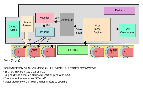
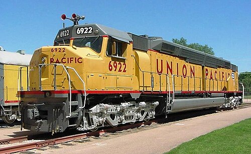
ディーゼル電気機関車では、ディーゼルエンジンが直流発電機(一般に牽引用に 3,000 馬力(2,200 kW)未満)または交流オルタネーター整流器(一般に 牽引用に 3,000 馬力以上)のいずれかを駆動し、その出力が機関車を駆動する牽引モーターに電力を供給します。ディーゼルエンジンと車輪の間には機械的な接続はありません。
ディーゼル電気推進の重要な構成要素は、ディーゼルエンジン(原動機とも呼ばれる)、主発電機/オルタネーター整流器、牽引モーター(通常4軸または6軸)、およびエンジン調速機と、牽引モーターへの電力供給を制御または変更するスイッチギア、整流器、およびその他のコンポーネントを含む電気または電子コンポーネントで構成される制御システムです。最も基本的なケースでは、非常に単純なスイッチギアのみを使用して、発電機をモーターに直接接続することができます。


当初、牽引モーターと発電機は直流機でした。1960年代に高容量シリコン整流器が開発され、直流発電機は、出力を直流に変換するダイオード ブリッジを使用する交流発電機に置き換えられました。この進歩により、機関車の信頼性が大幅に向上し、発電機の整流子とブラシが不要になったため、発電機の保守コストが削減されました。ブラシと整流子が不要になったことで、フラッシュオーバー (アーク故障とも呼ばれる) と呼ばれる特に破壊的なタイプの事象の可能性がなくなりました。フラッシュオーバーが発生すると、発電機がすぐに故障し、場合によっては機関室で火災が発生することがあります。
現在の北米の慣例では、高速旅客または「タイム」貨物には 4 つの車軸、低速または「マニフェスト」貨物には 6 つの車軸が使用されています。「タイム」貨物サービスで使用される最新のユニットは、フレームの下に 6 つの車軸を備えています。「マニフェスト」サービスで使用されるユニットとは異なり、「タイム」貨物ユニットでは、トラクション モーターに接続される車軸は 4 つだけで、残りの 2 つは重量配分用のアイドラー車軸となります。
1980 年代後半、高出力の可変電圧/可変周波数(VVVF) 駆動装置、つまり「トラクション インバータ」の開発により、多相 AC トラクション モーターの使用が可能になり、モーター整流子とブラシも不要になりました。その結果、メンテナンスが比較的少なく、旧式のモーターが破損することが多かった過負荷状態にも対処できる、より効率的で信頼性の高い駆動装置が誕生しました。
ディーゼル電気制御

ディーゼル電気機関車の出力は、ユニットの発電機の電流と電圧の制限を超えない限り、道路の速度とは無関係です。したがって、ユニットの牽引力(牽引バーの引っ張り力または牽引力とも呼ばれ、実際に列車を推進する力) を発生させる能力は、これらの制限内で速度と反比例して変化する傾向があります。 (下のパワー曲線を参照)。許容可能な動作パラメータを維持することは、初期のディーゼル電気機関車開発で解決する必要があった主要な設計上の考慮事項の 1 つであり、最終的には現代のユニットに導入されている複雑な制御システムにつながりました。
スロットル操作


原動機の出力は主に回転速度 ( RPM ) と燃料率によって決まり、調速機または類似の機構によって制御されます。調速機は、エンジン ドライバーによって決定されるスロットル設定と原動機の運転速度の両方に反応するように設計されています (制御理論を参照)。
機関車の出力、つまり速度は、通常、機関車の運転手が、スロットル位置に対応するバイナリのような電気信号を生成するステップ式または「ノッチ式」スロットルを使用して制御します。この基本設計は、編成内のすべてのユニットがスロットル位置に同じように反応することを保証する個別の条件を生成するため、複数ユニット(MU) 操作に適しています。バイナリ エンコーディングは、ユニットからユニットに信号を渡すために必要なトレインライン(電気接続) の数を最小限に抑えるのにも役立ちます。たとえば、スロットルが最大 14 段階ある場合、すべての可能なスロットル位置をエンコードするために必要なトレインラインは 4 つだけです。
EMDやゼネラル・エレクトリック社製のものなど、北米の機関車には、双方向に運転できるように 8 つのスロットル位置または「ノッチ」と「リバーサ」があります。英国製の機関車の多くには 10 位置スロットルがあります。機関車の乗務員は、スロットル設定に応じて、動力位置を「ラン 3」や「ノッチ 3」などと呼ぶことがよくあります。
古い機関車では、スロットル機構はラチェット式になっており、一度に 1 つ以上のパワー位置を進めることはできませんでした。たとえば、機関士はスロットルをノッチ 2 からノッチ 4 に引くと、ノッチ 3 で止まってしまいます。この機能は、急速なスロットル操作による突然のパワー増加 (多くの鉄道で運行規則違反となる「スロットル ストリッピング」) による列車の乱暴な操作を防ぐためのものでした。現代の機関車にはこの制限はなく、機関士がコントロールを操作する方法に関係なく 、制御システムがスムーズにパワーを調整し、列車の負荷の急激な変化を回避できます。
スロットルがアイドル位置にある場合、原動機は最小限の燃料しか受け取らず、低回転数でアイドリング状態になります。さらに、牽引モーターは主発電機に接続されておらず、発電機の界磁巻線は励起 (通電) されません。つまり、発電機は励起なしでは電気を生成しません。したがって、機関車は「ニュートラル」状態になります。概念的には、これはエンジンが作動しているときに自動車のトランスミッションをニュートラルにするのと同じです。
To set the locomotive in motion, the reverser control handle is placed into the correct position (forward or reverse), the brake is released and the throttle is moved to the run 1 position (the first power notch). An experienced engine driver can accomplish these steps in a coordinated fashion that will result in a nearly imperceptible start. The positioning of the reverser and movement of the throttle together is conceptually like shifting an automobile's automatic transmission into gear while the engine is idling.
Placing the throttle into the first power position will cause the traction motors to be connected to the main generator and the latter's field coils to be excited. With excitation applied, the main generator will deliver electricity to the traction motors, resulting in motion. If the locomotive is running "light" (that is, not coupled to the rest of a train) and is not on an ascending grade, it will easily accelerate. On the other hand, if a long train is being started, the locomotive may stall as soon as some of the slack has been taken up, as the drag imposed by the train will exceed the tractive force being developed. An experienced engine driver will be able to recognize an incipient stall and will gradually advance the throttle as required to maintain the pace of acceleration.
As the throttle is moved to higher power notches, the fuel rate to the prime mover will increase, resulting in a corresponding increase in RPM and horsepower output. At the same time, main generator field excitation will be proportionally increased to absorb the higher power. This will translate into increased electrical output to the traction motors, with a corresponding increase in tractive force. Eventually, depending on the requirements of the train's schedule, the engine driver will have moved the throttle to the position of maximum power and will maintain it there until the train has accelerated to the desired speed.
The propulsion system is designed to produce maximum traction motor torque at start-up, which explains why modern locomotives are capable of starting trains weighing in excess of 15,000 tons, even on ascending grades. Current technology allows a locomotive to develop as much as 30% of its loaded driver weight in tractive force, amounting to 120,000 pounds-force (530 kN) of tractive force for a large, six-axle freight (goods) unit. In fact, a consist of such units can produce more than enough drawbar pull at start-up to damage or derail cars (if on a curve) or break couplers (the latter being referred to in North American railroad slang as "jerking a lung"). Therefore, it is incumbent upon the engine driver to carefully monitor the amount of power being applied at start-up to avoid damage. In particular, "jerking a lung" could be a calamitous matter if it were to occur on an ascending grade, except that the safety inherent in the correct operation of fail-safe automatic train brakes installed in wagons today, prevents runaway trains by automatically applying the wagon brakes when train line air pressure drops.
Propulsion system operation

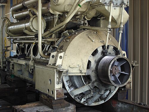

A locomotive's control system is designed so that the main generator electrical power output is matched to any given engine speed. Given the innate characteristics of traction motors, as well as the way in which the motors are connected to the main generator, the generator will produce high current and low voltage at low locomotive speeds, gradually changing to low current and high voltage as the locomotive accelerates. Therefore, the net power produced by the locomotive will remain constant for any given throttle setting (see power curve graph for notch 8).
In older designs, the prime mover's governor and a companion device, the load regulator, play a central role in the control system. The governor has two external inputs: requested engine speed, determined by the engine driver's throttle setting, and actual engine speed (feedback). The governor has two external control outputs: fuel injector setting, which determines the engine fuel rate, and current regulator position, which affects main generator excitation. The governor also incorporates a separate overspeed protective mechanism that will immediately cut off the fuel supply to the injectors and sound an alarm in the cab in the event the prime mover exceeds a defined RPM. Not all of these inputs and outputs are necessarily electrical.
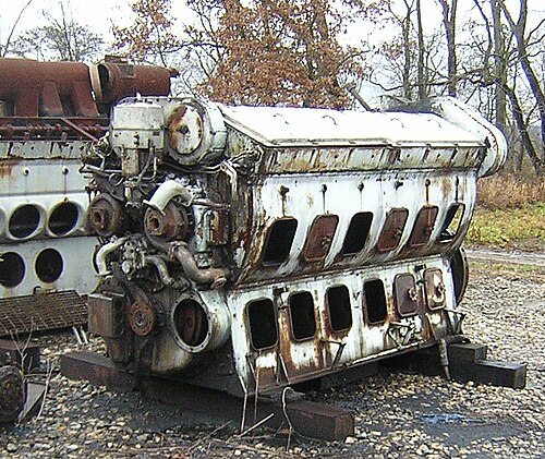
As the load on the engine changes, its rotational speed will also change. This is detected by the governor through a change in the engine speed feedback signal. The net effect is to adjust both the fuel rate and the load regulator position so that engine RPM and torque (and therefore power output) will remain constant for any given throttle setting, regardless of actual road speed.
In newer designs controlled by a "traction computer," each engine speed step is allotted an appropriate power output, or "kW reference", in software. The computer compares this value with actual main generator power output, or "kW feedback", calculated from traction motor current and main generator voltage feedback values. The computer adjusts the feedback value to match the reference value by controlling the excitation of the main generator, as described above. The governor still has control of engine speed, but the load regulator no longer plays a central role in this type of control system. However, the load regulator is retained as a "back-up" in case of engine overload. Modern locomotives fitted with electronic fuel injection (EFI) may have no mechanical governor; however, a "virtual" load regulator and governor are retained with computer modules.
Traction motor performance is controlled either by varying the DC voltage output of the main generator, for DC motors, or by varying the frequency and voltage output of the VVVF for AC motors. With DC motors, various connection combinations are utilized to adapt the drive to varying operating conditions.
At standstill, main generator output is initially low voltage/high current, often in excess of 1000 amperes per motor at full power. When the locomotive is at or near standstill, current flow will be limited only by the DC resistance of the motor windings and interconnecting circuitry, as well as the capacity of the main generator itself. Torque in a series-wound motor is approximately proportional to the square of the current. Hence, the traction motors will produce their highest torque, causing the locomotive to develop maximum tractive effort, enabling it to overcome the inertia of the train. This effect is analogous to what happens in an automobile automatic transmission at start-up, where it is in first gear and thereby producing maximum torque multiplication.
As the locomotive accelerates, the now-rotating motor armatures will start to generate a counter-electromotive force (back EMF, meaning the motors are also trying to act as generators), which will oppose the output of the main generator and cause traction motor current to decrease. Main generator voltage will correspondingly increase in an attempt to maintain motor power but will eventually reach a plateau. At this point, the locomotive will essentially cease to accelerate, unless on a downgrade. Since this plateau will usually be reached at a speed substantially less than the maximum that may be desired, something must be done to change the drive characteristics to allow continued acceleration. This change is referred to as "transition", a process that is analogous to shifting gears in an automobile.
Transition methods include:
- Series / Parallel or "motor transition".
- Initially, pairs of motors are connected in series across the main generator. At higher speed, motors are reconnected in parallel across the main generator.
- "Field shunting", "field diverting", or "weak fielding".
- Resistance is connected in parallel with the motor field. This has the effect of increasing the armature current, producing a corresponding increase in motor torque and speed.
Both methods may also be combined, to increase the operating speed range.
- Generator / rectifier transition
- Reconnecting the two separate internal main generator stator windings of two rectifiers from parallel to series to increase the output voltage.
In older locomotives, it was necessary for the engine driver to manually execute transition by use of a separate control. As an aid to performing transition at the right time, the load meter (an indicator that shows the engine driver how much current is being drawn by the traction motors) was calibrated to indicate at which points forward or backward transition should take place. Automatic transition was subsequently developed to produce better-operating efficiency and to protect the main generator and traction motors from overloading from improper transition.
Modern locomotives incorporate traction inverters, AC to DC, capable of delivering 1,200 volts (earlier traction generators, DC to DC, were capable of delivering only 600 volts). This improvement was accomplished largely through improvements in silicon diode technology. With the capability of delivering 1,200 volts to the traction motors, the need for "transition" was eliminated.
Dynamic braking
A common option on diesel–electric locomotives is dynamic (rheostatic) braking.
Dynamic braking takes advantage of the fact that the traction motor armatures are always rotating when the locomotive is in motion and that a motor can be made to act as a generator by separately exciting the field winding. When dynamic braking is used, the traction control circuits are configured as follows:
- The field winding of each traction motor is connected across the main generator.
- The armature of each traction motor is connected across a forced-air-cooled resistance grid (the dynamic braking grid) in the roof of the locomotive's hood.
- The prime mover RPM is increased, and the main generator field is excited, causing a corresponding excitation of the traction motor fields.
The aggregate effect of the above is to cause each traction motor to generate electric power and dissipate it as heat in the dynamic braking grid. A fan connected across the grid provides forced-air cooling. Consequently, the fan is powered by the output of the traction motors and will tend to run faster and produce more airflow as more energy is applied to the grid.
Ultimately, the source of the energy dissipated in the dynamic braking grid is the motion of the locomotive as imparted to the traction motor armatures. Therefore, the traction motors impose drag and the locomotive acts as a brake. As speed decreases, the braking effect decays and usually becomes ineffective below approximately 16 km/h (10 mph), depending on the gear ratio between the traction motors and axles.
Dynamic braking is particularly beneficial when operating in mountainous regions, where there is always the danger of a runaway due to overheated friction brakes during descent. In such cases, dynamic brakes are usually applied in conjunction with the air brakes, the combined effect being referred to as blended braking. The use of blended braking can also assist in keeping the slack in a long train stretched as it crests a grade, helping to prevent a "run-in", an abrupt bunching of train slack that can cause a derailment. Blended braking is also commonly used with commuter trains to reduce wear and tear on the mechanical brakes that is a natural result of the numerous stops such trains typically make during a run.
Electro-diesel

These special locomotives can operate as an electric locomotive or as a diesel locomotive. The Long Island Rail Road, Metro-North Railroad and New Jersey Transit Rail Operations operate dual-mode diesel–electric/third-rail (catenary on NJTransit) locomotives between non-electrified territory and New York City because of a local law banning diesel-powered locomotives in Manhattan tunnels. For the same reason, Amtrak operates a fleet of dual-mode locomotives in the New York area. British Rail operated dual diesel–electric/electric locomotives designed to run primarily as electric locomotives with reduced power available when running on diesel power. This allowed railway yards to remain unelectrified, as the third rail power system is extremely hazardous in a yard area.
Diesel–hydraulic

Diesel–hydraulic locomotives use one or more torque converters, in combination with fixed ratio gears. Drive shafts and gears form the final drive to convey the power from the torque converters to the wheels, and to effect reverse. The difference between hydraulic and mechanical systems is where the speed and torque is adjusted. In the mechanical transmission system that has multiple ratios such as in a gear box, if there is a hydraulic section, it is only to allow the engine to run when the train is too slow or stopped. In the hydraulic system, hydraulics are the primary system for adapting engine speed and torque to the train's situation, with gear selection for only limited use, such as reverse gear.
Hydrostatic transmission
Hydraulic drive systems using a hydrostatic hydraulic drive system have been applied to rail use. Modern examples included 350 to 750 hp (260 to 560 kW) shunting locomotives by Cockerill (Belgium),[43] 4 to 12 tonne 35 to 58 kW (47 to 78 hp) narrow gauge industrial locomotives by Atlas Copco subsidiary GIA.[44] Hydrostatic drives are also utilised in railway maintenance machines (tampers, rail grinders).[45]
Application of hydrostatic transmissions is generally limited to small shunting locomotives and rail maintenance equipment, as well as being used for non-tractive applications in diesel engines such as drives for traction motor fans.[citation needed]
Hydrokinetic transmission

1 — diesel, 2 — oil filter, 3 — turning gear, 4 — water-to-fuel heater, 5 — auxiliary electric generator, 6 — hydrokinetic transmission, 7 — first gear valve (with manual shift handle), 8 — automatic transmission oil filter
Hydrokinetic transmission (also called hydrodynamic transmission) uses a torque converter. A torque converter consists of three main parts, two of which rotate, and one (the stator) that has a lock preventing backwards rotation and adding output torque by redirecting the oil flow at low output RPM. All three main parts are sealed in an oil-filled housing. To match engine speed to load speed over the entire speed range of a locomotive some additional method is required to give sufficient range. One method is to follow the torque converter with a mechanical gearbox which switches ratios automatically, similar to an automatic transmission in an automobile. Another method is to provide several torque converters each with a range of variability covering part of the total required; all the torque converters are mechanically connected all the time, and the appropriate one for the speed range required is selected by filling it with oil and draining the others. The filling and draining is carried out with the transmission under load, and results in very smooth range changes with no break in the transmitted power.
-
 Diesel prime mover (left) and hydraulic transmission (right) of the British Rail Class 52 diesel locomotive
 -
 South African Class 61-000 diesel-hydraulic locomotive under construction
_1.jpg/500px-SAR_Class_61-000_61-006_(D750)_1.jpg)
Locomotives
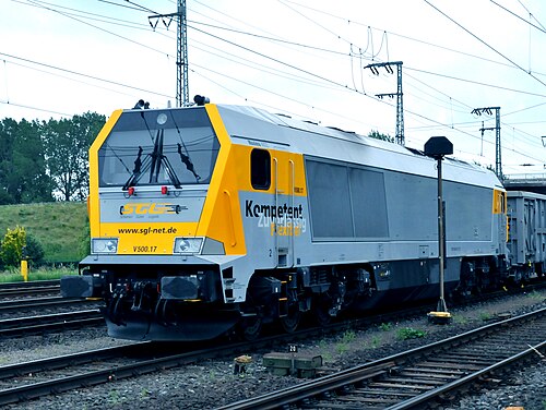
Whilst Diesel Electric (DE) locomotives were chosen around most of the world, a few countries turned toward Diesel Hydraulic (DH) locomotives instead, most notably Germany, Finland & Japan, as well as Britain for a time.
The reasons for this were multiple, two of the more notable being that whilst most DH locomotives achieved about the same drivetrain efficiency as DEs of around ~85% (with some early British designs being the exception), they could at the same time be built noticeably lighter for the same total power output. This was the case as the hydraulic transmissions didn't weigh nearly as much as the combination of generator(s) & multiple electric traction motors necessary on a DE.
The second notable advantage with DH locomotives, which lasted up until the introduction of modern traction control systems, was increased adhesion/traction pr unit of weight. Normally on a DE locomotive every powered axle on a bogey features its own separate traction motor with no linkage between axles, and as such there is the potential that if one wheel loses grip and slips, this will cause the axle to spin faster independently from the others, resulting in a significant loss of overall traction. By contrast on a DH locomotive all the axles on each bogey are linked together via coupled drive shafts, and as such no single axle can begin to spin faster on its own should its wheels hit a slippery spot, greatly helping with traction. Prior to the introduction of effective traction control systems this technical difference alone could contribute anywhere between a 15-33% increase to the factor of adhesion for a diesel-hydraulic versus a diesel-electric locomotive.
These two advantages were some of the main reasons why in the 1960's three major US railroad companies, incl. Southern Pacific, initially expressed great interest in diesel hydraulic locomotive designs, eventually leading to the order and purchase of several West German ML4000 DH locomotives built specifically for the US by the firm Krauss Maffei. Reliability problems with these machines during high altitude operations with SP in the US, as well as the advent of domestic diesel engines of similar power levels coupled with an industry better suited for supporting diesel electric powertrains, however, meant that eventually interest in diesel hydraulics faded away in the US.
In Germany and Finland however, diesel–hydraulic systems achieved a very high reliability in operation, similar to or even better than DEs, which when coupled with the DHs aforementioned technical advantages helped make it the more popular type of diesel locomotive in these countries for a long time. Meanwhile in the UK the diesel–hydraulic principle gained a more mixed reputation.
By the 21st century, for diesel locomotive traction worldwide the majority of countries used diesel–electric designs, with diesel-hydraulic designs not found in use outside Germany, Finland and Japan, and some neighbouring states, where it is used in designs for freight work.
Diesel–hydraulic locomotives have a smaller market share than diesel electrics – the main worldwide user of main-line hydraulic transmissions has been the Federal Republic of Germany, with designs including the 1950s DB class V 200, and the 1960 and 1970s DB Class V 160 family. British Rail introduced a number of diesel-hydraulic designs during its 1955 Modernisation Plan, initially license-built versions of German designs (see Category:Diesel–hydraulic locomotives of Great Britain). In Spain, Renfe used high power to weight ratio twin-engine German designs to haul high speed trains from the 1960s to 1990s. (See Renfe Classes 340, 350, 352, 353, 354)
Other main-line locomotives of the post-war period included the 1950s GMD GMDH-1 experimental locomotives; the Henschel & Son built South African Class 61-000; in the 1960s Southern Pacific bought 18 Krauss-Maffei KM ML-4000 diesel–hydraulic locomotives. The Denver & Rio Grande Western Railroad also bought three, all of which were later sold to SP.[47]
In Finland, over 200 Finnish-built VR class Dv12 and Dr14 diesel–hydraulics with Voith transmissions have been continuously used since the early 1960s. All units of Dr14 class and most units of Dv12 class are still in service. VR has abandoned some weak-conditioned units of 2700 series Dv12s.[48]
In the 21st century series production standard gauge diesel–hydraulic designs include the Voith Gravita, ordered by Deutsche Bahn, and the Vossloh G2000 BB, G1206 and G1700 designs, all manufactured in Germany for freight use.
-
 JNR DD51 1 diesel-hydraulic
 -
 DB class V 200 diesel–hydraulic locomotive
 -
 British Rail diesel–hydraulic locomotives: Class 52 "Western", Class 42 "Warship" and Class 35 "Hymek"
 -
 A VR Class Dv12 diesel–hydraulic locomotive
 -
 A GMD GMDH-1 diesel–hydraulic locomotive
 -
 A Soviet diesel-hydraulic locomotive TGM23
.jpg/500px-%D0%A2%D0%93%D0%9C23%D0%91-2954,_%D0%9B%D0%B8%D1%82%D0%B2%D0%B0,_%D0%9F%D0%B0%D0%BD%D0%B5%D0%B2%D0%B5%D0%B6%D1%81%D0%BA%D0%B8%D0%B9_%D1%83%D0%B5%D0%B7%D0%B4,_%D0%BF%D0%BE%D0%B4%D1%8A%D0%B5%D0%B7%D0%B4%D0%BD%D0%BE%D0%B9_%D0%BF%D1%83%D1%82%D1%8C_%D0%BE%D1%82_%D1%81%D1%82%D0%B0%D0%BD%D1%86%D0%B8%D0%B8_%D0%A0%D0%BE%D0%BA%D0%B8%D1%88%D0%BA%D0%B8%D1%81_(Trainpix_142683).jpg)
Multiple units
Diesel–hydraulic drive is common in multiple units, with various transmission designs used including Voith torque converters, and fluid couplings in combination with mechanical gearing.
The majority of British Rail's second generation passenger DMU stock used hydraulic transmission. In the 21st century, designs using hydraulic transmission include Bombardier's Turbostar, Talent, RegioSwinger families; diesel engined versions of the Siemens Desiro platform, and the Stadler Regio-Shuttle.
Diesel–steam
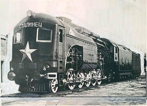
Steam-diesel hybrid locomotives can use steam generated from a boiler or diesel to power a piston engine. The Cristiani Compressed Steam System used a diesel engine to power a compressor to drive and recirculate steam produced by a boiler; effectively using steam as the power transmission medium, with the diesel engine being the prime mover[49]
Diesel–pneumatic
The diesel-pneumatic locomotive was of interest in the 1930s because it offered the possibility of converting existing steam locomotives to diesel operation. The frame and cylinders of the steam locomotive would be retained and the boiler would be replaced by a diesel engine driving an air compressor. The problem was low thermal efficiency because of the large amount of energy wasted as heat in the air compressor. Attempts were made to compensate for this by using the diesel exhaust to re-heat the compressed air but these had limited success. A German proposal of 1929 did result in a prototype[50] but a similar British proposal of 1932, to use an LNER Class R1 locomotive, never got beyond the design stage.
Multiple-unit operation
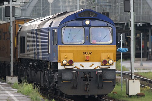
Most diesel locomotives are capable of multiple-unit operation (MU) as a means of increasing horsepower and tractive effort when hauling heavy trains. All North American locomotives, including export models, use a standardized AAR electrical control system interconnected by a 27-pin MU cable between the units. For UK-built locomotives, a number of incompatible control systems are used, but the most common is the Blue Star system, which is electro-pneumatic and fitted to most early diesel classes. A small number of types, typically higher-powered locomotives intended for passenger only work, do not have multiple control systems. In all cases, the electrical control connections made common to all units in a consist are referred to as trainlines. The result is that all locomotives in a consist behave as one in response to the engine driver's control movements.
The ability to couple diesel–electric locomotives in an MU fashion was first introduced in the EMC EA/EB of 1937. Electrical interconnections were made so one engine driver could operate the entire consist from the head-end unit.
In mountainous regions, it is common to interpose helper locomotives in the middle of the train, both to provide the extra power needed to ascend a grade and to limit the amount of stress applied to the draft gear of the car coupled to the head-end power. The helper units in such distributed power configurations are controlled from the lead unit's cab through coded radio signals. Although this is technically not an MU configuration, the behaviour is the same as with physically interconnected units.
Cab arrangements
Cab arrangements vary by builder and operator. Practice in the U.S. has traditionally been for a cab at one end of the locomotive with limited visibility if the locomotive is not operated cab forward. This is not usually a problem as U.S. locomotives are usually operated in pairs, or threes, and arranged so that a cab is at each end of each set. European practice is usually for a cab at each end of the locomotive as trains are usually light enough to operate with one locomotive. Early U.S. practice was to add power units without cabs (booster or B units) and the arrangement was often A-B, A-A, A-B-A, A-B-B, or A-B-B-A where A was a unit with a cab. Center cabs were sometimes used for switch locomotives.
Cow-calf
_Cow_and_Calf_at_Riverside_Yard,_Baltimore_(22341847029).jpg/500px-Baltimore_and_Ohio_9624_(TR4)_Cow_and_Calf_at_Riverside_Yard,_Baltimore_(22341847029).jpg)
In North American railroading, a cow-calf set is a pair of switcher-type locomotives: one (the cow) equipped with a driving cab, the other (the calf) without a cab, and controlled from the cow through cables. Cow-calf sets are used in heavy switching and hump yard service. Some are radio controlled without an operating engineer present in the cab. This arrangement is also known as master–slave. Where two connected units were present, EMD called these TR-2s (approximately 2,000 hp or 1,500 kW); where three units, TR-3s (approximately 3,000 hp or 2,200 kW).
Cow-calves have largely disappeared as these engine combinations exceeded their economic lifetimes many years ago.
Present North American practice is to pair two 3,000 hp GP40-2 or SD40-2 road switchers, often nearly worn-out and very soon ready for rebuilding or scrapping, and to utilize these for so-called "transfer" uses, for which the TR-2, TR-3 and TR-4 engines were originally intended, hence the designation TR, for "transfer".
Occasionally, the second unit may have its prime-mover and traction alternator removed and replaced by concrete or steel ballast and the power for traction obtained from the master unit. As a 16-cylinder prime-mover generally weighs in the 36,000-pound (16,000 kg) range, and a 3,000 hp traction alternator generally weighs in the 18,000-pound (8,200 kg) range, this would mean that 54,000 lb (24,000 kg) would be needed for ballast.
A pair of fully capable "Dash 2" units would be rated 6,000 hp (4,500 kW). A "Dash 2" pair where only one had a prime-mover/alternator would be rated 3,000 hp, with all power provided by master, but the combination benefits from the tractive effort provided by the slave as engines in transfer service are seldom called upon to provide 3,000 hp much less 6,000 hp on a continuous basis.
Fittings and appliances
Flameproofing
A standard diesel locomotive presents a very low fire risk but "flame proofing" can reduce the risk even further. This involves fitting a water-filled box to the exhaust pipe to quench any red-hot carbon particles that may be emitted. Other precautions may include a fully insulated electrical system (neither side earthed to the frame) and all electric wiring enclosed in conduit.
The flameproof diesel locomotive has replaced the fireless steam locomotive in areas of high fire risk such as oil refineries and ammunition dumps. Preserved examples of flameproof diesel locomotives include:
- Francis Baily of Thatcham (ex-RAF Welford) at Southall Railway Centre
- Naworth (ex-National Coal Board) at the South Tynedale Railway[51]
Latest development of the "Flameproof Diesel Vehicle Applied New Exhaust Gas Dry Type Treatment System" does not need the water supply.[52]
Lights
.jpg/500px-Canadian_National_diesels_southbound_on_the_Norfolk_Southern_near_Polaris_Mall_in_Columbus,_Ohio_(2092116881).jpg)
The lights fitted to diesel locomotives vary from country to country. North American locomotives are fitted with two headlights (for safety in case one malfunctions) and a pair of ditch lights. The latter are fitted low down at the front and are designed to make the locomotive easily visible as it approaches a grade crossing. Older locomotives may be fitted with a Gyralite or Mars Light instead of the ditch lights.
Environmental impact

Although diesel locomotives generally emit less sulphur dioxide, a major pollutant to the environment, and greenhouse gases than steam locomotives, they still emit large amounts.[53] Furthermore, like other diesel powered vehicles, they emit nitrogen oxides and fine particles, which are a risk to public health. In fact, in this last respect diesel locomotives may perform worse than steam locomotives.
For years, it was thought by American government scientists who measure air pollution that diesel locomotive engines were relatively clean and emitted far less health-threatening emissions than those of diesel trucks or other vehicles; however, the scientists discovered that because they used faulty estimates of the amount of fuel consumed by diesel locomotives, they grossly understated the amount of pollution generated annually. After revising their calculations, they concluded that the annual emissions of nitrogen oxide, a major ingredient in smog and acid rain, and soot would be by 2030 nearly twice what they originally assumed.[54][55] In Europe, where most major railways have been electrified, there is less concern.
This would mean that in the USA diesel locomotives would be releasing more than 800,000 tons of nitrogen oxide and 25,000 tons of soot every year within a quarter of a century, in contrast to the EPA's previous projections of 480,000 tons of nitrogen dioxide and 12,000 tons of soot. Since this was discovered, to reduce the effects of the diesel locomotive on humans (who are breathing the noxious emissions) and on plants and animals, it is considered practical to install traps in the diesel engines to reduce pollution levels[56] and other methods of pollution control (e.g., use of biodiesel).
Diesel locomotive pollution has been of particular concern in the city of Chicago. The Chicago Tribune reported levels of diesel soot inside locomotives leaving Chicago at levels hundreds of times above what is normally found on streets outside.[57] Residents of several neighborhoods are most likely exposed to diesel emissions at levels several times higher than the national average for urban areas.[58]
Mitigation
In 2008, the United States Environmental Protection Agency (EPA) mandated regulations requiring all new or refurbished diesel locomotives to meet Tier II pollution standards that slash the amount of allowable soot by 90% and require an 80% reduction in nitrogen oxide emissions. See List of low emissions locomotives.
Other technologies that are being deployed to reduce diesel locomotive emissions and fuel consumption include "Genset" switching locomotives and hybrid Green Goat designs. Genset locomotives use multiple smaller high-speed diesel engines and generators (generator sets), rather than a single medium-speed diesel engine and a single generator.[59] Because of the cost of developing clean engines, these smaller high-speed engines are based on already developed truck engines. Green Goats are a type of hybrid switching locomotive utilizing a small diesel engine and a large bank of rechargeable batteries.[60][61] Switching locomotives are of particular concern as they typically operate in a limited area, often in or near urban centers, and spend much of their time idling. Both designs reduce pollution below EPA Tier II standards and cut or eliminate emissions during idle.
Advantages over steam
As diesel locomotives advanced, the cost of manufacturing and operating them dropped, and they became cheaper to own and operate than steam locomotives. In North America, steam locomotives were custom-made for specific railway routes, so economies of scale were difficult to achieve.[62] Though more complex to produce with exacting manufacturing tolerances (1⁄10000-inch or 0.0025-millimetre for diesel, compared with 1⁄100-inch (0.25 mm) for steam), diesel locomotive parts were easier to mass-produce. Baldwin Locomotive Works offered almost 500 steam models in its heyday, while EMD offered fewer than ten diesel varieties.[63] In the United Kingdom, British Railways built steam locomotives to standard designs from 1951 onwards. These included standard, interchangeable parts, making them cheaper to produce than the diesel locomotives then available. The capital cost per drawbar horse power was £13 6s (steam), £65 (diesel), £69 7s (turbine) and £17 13s (electric).[64]
Diesel locomotives offer significant operating advantages over steam locomotives.[65] They can safely be operated by one person, making them ideal for switching/shunting duties in yards (although for safety reasons many main-line diesel locomotives continue to have two-person crews: an engineer and a conductor/switchman) and the operating environment is much more attractive, being quieter, fully weatherproof and without the dirt and heat that is an inevitable part of operating a steam locomotive. Diesel locomotives can be worked in multiple with a single crew controlling multiple locomotives in a single train – something not practical with steam locomotives. This brought greater efficiencies to the operator, as individual locomotives could be relatively low-powered for use as a single unit on light duties but marshaled together to provide the power needed on a heavy train. With steam traction, a single very powerful and expensive locomotive was required for the heaviest trains, or the operator resorted to double heading with multiple locomotives and crews, a method which was also expensive and brought with it its own operating difficulties.
Diesel engines can be started and stopped almost instantly, meaning that a diesel locomotive has the potential to incur no fuel costs when not being used. However, it is still the practice of large North American railroads to use straight water as a coolant in diesel engines instead of coolants that incorporate anti-freezing properties; this results in diesel locomotives being left idling when parked in cold climates instead of being completely shut down. A diesel engine can be left idling unattended for hours or even days, especially since practically every diesel engine used in locomotives has systems that automatically shut the engine down if problems such as a loss of oil pressure or coolant loss occur. Automatic start/stop systems are available which monitor coolant and engine temperatures. When the unit is close to having its coolant freeze, the system restarts the diesel engine to warm the coolant and other systems.[66]
Steam locomotives require intensive maintenance, lubrication, and cleaning before, during, and after use. Preparing and firing a steam locomotive for use from cold can take many hours. They can be kept in readiness between uses with a low fire, but this requires regular stoking and frequent attention to maintain the level of water in the boiler. This may be necessary to prevent the water in the boiler freezing in cold climates, so long as the water supply is not frozen. After use a steam locomotive requires a lengthy disposal operation to perform cleaning, inspection, maintenance and refilling with water and fuel before it is ready for its next duty. By contrast, as early as 1939 EMD was promoting its FT Series locomotive as needing no maintenance between 30-day inspections beyond refuelling and basic fluid level and safety checks which could be performed with the prime mover still running. Railways converting from steam to diesel operation in the 1940s and 1950s found that for a given period diesel locomotives were available for, on average, three or four times more revenue-earning hours than equivalent steam locomotives, allowing locomotive fleets to be cut drastically in size while maintaining operational capacity.[citation needed]
The maintenance and operational costs of steam locomotives were much higher than diesels. Annual maintenance costs for steam locomotives accounted for 25% of the initial purchase price. Spare parts were cast from wooden masters for specific locomotives. The sheer number of unique steam locomotives meant that there was no feasible way for spare-part inventories to be maintained.[67] With diesel locomotives spare parts could be mass-produced and held in stock ready for use and many parts and sub-assemblies could be standardized across an operator's fleet using different models of locomotive from the same builder. Modern diesel locomotive engines are designed to allow the power assemblies (systems of working parts and their block interfaces) to be replaced while keeping the main block in the locomotive, which greatly reduces the time that a locomotive is out of revenue-generating service when it requires maintenance.[34]
Steam engines required large quantities of coal and water, which were expensive variable operating costs.[68] Further, the thermal efficiency of steam was considerably less than that of diesel engines. Diesel's theoretical studies demonstrated potential thermal efficiencies for a compression ignition engine of 36% (compared with 6–10% for steam), and an 1897 one-cylinder prototype operated at a remarkable 26% efficiency.[69]
However, one study published in 1959 suggested that many of the comparisons between diesel and steam locomotives were made unfairly, mostly because diesels were a newer technology. After painstaking analysis of financial records and technological progress, the author found that if research had continued on steam technology instead of diesel, there would be negligible financial benefit in converting to diesel locomotion.[70]
By the mid-1960s, diesel locomotives had effectively replaced steam locomotives where electric traction was not in use.[68] Attempts to develop advanced steam technology continue in the 21st century but have not had a significant effect.
See also
References
- ^ "World's fastest diesel locomotive will run again at Ruddington". BBC News. British Broadcasting Corporation. 16 July 2021. Retrieved 22 July 2023.
- ^ U.S. 608,845, Rudolf Diesel, "Internal-combustion engine", issued 9 August 1898
- ^ Arnold Heller: Der Automobilmotor im Eisenbahnbetriebe, Leipzig 1906, reprinted by Salzwasserverlag 2011, ISBN 978-3-86444-240-7
- ^ Röll: Enzyklopädie des Eisenbahnwesens → Elektrische Eisenbahnen, there go to VII. Automobile Triebwagen → zu b Benzin-, Benzol- oder Gasolin-elektrischen Triebwagen
- ^ Raymond S Zeitler, American School (Chicago, Ill.): Self-Contained Railway Motor Cars and Locomotives, section SELF-CONTAINED RAILWAY CARS 57–59
- ^ Röll: Arader und Csanáder Eisenbahnen Vereinigte Aktien-Gesellschaft
- ^ Museal railcars of BHÉV and their history
- ^ "Diesel-Electric Locomotives". Diesel-Electric Locomotives. Union Pacific. Retrieved 12 May 2022.
- ^ "Motive power for British Railways" (PDF), The Engineer, vol. 202, p. 254, 24 April 1956, archived from the original (PDF) on 4 March 2014, retrieved 28 February 2014
- ^ The Electrical Review, 22: 474, 4 May 1888,
A small double cylinder engine has been mounted upon a truck, which is worked on a temporary line of rails, in order to show the adaptation of a petroleum engine for locomotive purposes, on tramways
{{citation}}: Missing or empty|title=(help) - ^ Diesel Railway Traction, 17: 25, 1963,
In one sense a dock authority was the earliest user of an oil-engined locomotive, for it was at the Hull docks of the North Eastern Railway that the Priestman locomotive put in its short period of service in 1894
{{citation}}: Missing or empty|title=(help) - ^ Day, John R.; Cooper, Basil Knowlman (1960), railway Locomotives, Frederick Muller, p. 42,
The diesel has quite a long history, and the first one ran as far back as 1894. This was a tiny 30-h.p. two-axle standard-gauge locomotive with a two- cylinder engine designed by William Dent Priestman
- ^ Webb, Brian (1973). The British Internal Combustion Locomotive 1894–1940. David & Charles. ISBN 978-0715361153.
- ^ Diesel, Rudolf Christian Karl (1893), Theorie und Konstruktion eines rationellen Wärmemotors zum Ersatz der Dampfmaschine und der heute bekannten Verbrennungsmotoren (in German), Berlin: Springer, pp. 89–91, ISBN 978-3-642-64941-7
- ^ Churella 1998, p. 15.
- ^ Churella 1998, p. 12.
- ^ Glatte, Wolfgang (1993). Deutsches Lok-Archiv: Diesellokomotiven 4. Auflage. Berlin: Transpress. ISBN 978-3-344-70767-5.
- ^ "DD50 5 DD50 2|随時アップ:消えた車輌写真館|鉄道ホビダス". rail.hobidas.com.
- ^ "キハ43000の資料 – しるねこの微妙な生活/浮気心あれば水心!?". Archived from the original on 2016-06-25. Retrieved 2013-01-09.
- ^ "vecchia loco ferrovie della Calabria – Ferrovie.it". www.ferrovie.it.
- ^ Messerschmitt, Wolfgang (1969). Geschichte der italienischen Elektro- und Diesellokomotiven [History of Italy's electric and Diesel locomotives] (in German). Zürich: Orell Füesli Verlag. pp. 101–102.
- ^ "The first russian diesel locos". izmerov.narod.ru.
- ^ a b Stover, John F. (1997). American Railroads. Chicago: University of Chicago Press. p. 212. ISBN 978-0-226-77658-3.
- ^ Edison, Thomas A. U.S. Patent No. 493,425, filed January 19, 1891, and issued March 14, 1891 Accessed via the Edison Papers at: US Patent #493,425 on February 8, 2007.
- ^ Lemp, Hermann. U.S. Patent No. 1,154,785, filed April 8, 1914, and issued September 28, 1915. Accessed via Google Patent Search at: US Patent #1,154,785 on February 8, 2007.
- ^ Pinkepank 1973, pp. 139–141
- ^ Churella 1998, pp. 25–27.
- ^ Evolution of the American Diesel Locomotive, J Parker Lamb 2007, Indiana University Press, ISBN 978-0-253-34863-0, p.29
- ^ Churella 1998, pp. 28–30.
- ^ "Railroads To Try Diesel Locomotive", Special to the New York Times, p. 1, February 18, 1925
- ^ Pinkepank 1973, p. 283.
- ^ Churella 1998, p. 27.
- ^ Pinkepank 1973, p. 409.
- ^ a b Kettering, E.W. (29 November 1951). History and Development of the 567 Series General Motors Locomotive Engine. ASME 1951 Annual Meeting. Atlantic City, New Jersey: Electro-Motive Division, General Motors Corporation.
- ^ "Diesel Streamliners Now Link Coast-to-Coast" Popular Mechanics, August 1937
- ^ Pinkepank 1973, p. 209–211.
- ^ Solomon, Brian, Locomotive, 2001, pp 120, 130
- ^ Burke, A 1991., Rails through the Wilderness; New South Wales University Press
- ^ Holden, R 2006 No. 259 : the curious story of a forgotten locomotive, Railmac Publications
- ^ Rail Motors and XPTs, David Cooke, ARHS, NSW Division, 1984 pp40-59
- ^ Solomon, Brian (15 June 2016). "EMD DDA40X". The field guide to trains : locomotives and rolling stock. Minneapolis, Minnesota. p. 189. ISBN 9780760349977. OCLC 928614280.
{{cite book}}: CS1 maint: location missing publisher (link) - ^ Рекордные испытания ТЭП80-0002 05.10.1993.TEP80 world speed record 271 km/h on YouTube
- ^ "Shunting locomotives". www.cmigroupe.com. Retrieved 29 June 2019.
- ^ "Locomotives", www.gia.se, archived from the original on 2014-03-30, retrieved 1 February 2014
- ^ Solomon, Brian (2001), Railway Maintenance Equipment: The Men and Machines That Keep the Railroads Running, Voyager Press, pp. 78, 96, ISBN 978-0760309759
- ^ "Voith Maxima product folder". Voith Turbo Lokomotivtechnik. August 2010. Retrieved 2011-01-18.
- ^ Marre, Louis A. (1995). Diesel Locomotives: The First Fifty Years. Waukesha, Wis., USA: Kalmbach. pp. 384–385. ISBN 978-0-89024-258-2.
- ^ Suruliputus saatteli veturit viimeiselle matkalle (in Finnish)
- ^ The Paragon-Cristiani Compressed Steam System Archived 2017-12-11 at the Wayback Machine dslef.dsl.pipex.com
- ^ "A German Diesel-Pneumatic Locomotive". Douglas-self.com. Retrieved 2011-08-20.
- ^ "UK Money Guide – Borrow Money Today". Archived from the original on January 6, 2009. Retrieved January 17, 2009.
- ^ "Development of the Flameproof Diesel Vehicle Applied New Exhaust Gas Dry Type Treatment System". Sciencelinks.jp. 2009-03-18. Archived from the original on 2012-02-17. Retrieved 2011-08-20.
- ^ King, Joe (2008-09-22). "Engineering gets $1 million grant to make locomotives leaner, greener". Northern Illinois University. Archived from the original on 2012-09-10. Retrieved 2011-08-06.
- ^ Eilperin, Juliet (2006-08-14). "Attention to Locomotives' Emissions Renewed". The Washington Post. Retrieved 2011-08-06.
- ^ Hawthorne, Michael (February 14, 2011). "Metra finds 'alarming' pollution on some trains". Chicago Tribune. Retrieved 2011-08-06.
- ^ Wilkins, Davell (2011-04-13). "Study: Installed Traps In Diesel Engines Reduce Pollution Levels". Top News. Retrieved 2011-08-06.
- ^ "Pollution on Metra Trains Worse Than Thought: Report". Fox Chicago News. 2011-02-14. Retrieved 2011-08-06.
- ^ Lydersen, Kari (April 21, 2011). "Black Carbon Testing Finds High Levels". The New York Times. Retrieved August 6, 2011.
- ^ "Multi-Engine GenSet Ultra Low Emissions Road-Switcher Locomotive" (PDF). National Railway Equipment Company. Archived from the original (PDF) on 2012-02-10. Retrieved 2012-06-03.
- ^ "Railpower Technologies Products". Archived from the original on January 14, 2008. Retrieved 2012-06-03.
- ^ RJ Corman Railpower Genset & Hybrid Switchers. Trainweb.org. Retrieved on 2013-08-16.
- ^ Churella 1998, p. 10.
- ^ Churella 1998, p. 19.
- ^ "Standardisation and Comparative Costs of Motive Power on B.R.". Railway Magazine: 60–61. January 1951.
- ^ http://www.sdrm.org/faqs/hostling.html Archived 2011-01-30 at the Wayback Machine, Phil Jern "How to Boot a Steam Locomotive" (1990) San Diego Railroad Museum.
- ^ SmartStart® IIe – Automatic Engine Start/Stop System Archived 2012-07-21 at the Wayback Machine. Ztr.com. Retrieved on 2013-08-16.
- ^ Churella 1998, pp. 12–17.
- ^ a b Stover, 213
- ^ Churella 1998, p. 14.
- ^ Brown, H. F. (1959). Economic results of diesel–electric motive power on the railways in the United States. Proceedings of the Institution of Mechanical Engineers, 175(1), 257-317. doi:10.1243/PIME_PROC_1961_175_025_02
Sources
- Churella, Albert J. (1998). From Steam to Diesel: Managerial Customs and Organizational Capabilities in the Twentieth-Century American Locomotive Industry. Princeton, New Jersey: Princeton University Press. ISBN 978-0-691-02776-0.
- Pinkepank, Jerry A. (1973). The Second Diesel Spotter's Guide. Milwaukee WI: Kalmbach Books. ISBN 978-0-89024-026-7.
External links
Wikimedia Commons has media related to Diesel locomotives.
- US Government test of GP38-2 locomotive with biodiesel fuel.
- A 1926 article The Diesel Engine in Railway Transportation on Diesel locomotives
- Diesel locomotive