
Loading article…
ジェットエンジンは、燃料を推力に変換することで機能します。その性能は、燃料の無駄の割合を示します。ジェット エンジンは、燃焼した燃料の熱をエンジンを通過する空気に伝達します。その過程で、車両を推進する際に推力を生み出しますが、多くの燃料が無駄になり、熱としてしか現れません。推進エンジニアは、燃料エネルギーが使用できない熱エネルギーに劣化するのを最小限に抑えることを目指しています。1970 年代に燃料価格が上昇したため、民間航空機の性能向上が重視されるようになりました。
ジェットエンジンの性能の意味は「ジェットエンジン会社が販売する最終製品」[1]と表現されており、その基準には推力と燃料消費、寿命、重量、排出量、直径、コストが含まれます。性能基準はエンジンの設計に使用される技術レベルを反映しており、ジェットエンジンが1940年代に運用されて以来、技術は継続的に進歩しています。性能のカテゴリには、性能の向上、性能の低下、性能の維持、エンジン単体の性能(未インストール)、航空機の動力装置の一部としての性能(インストール済み)が含まれます。
パイロット向けのジェットエンジン性能(推力と燃料消費量)は、コックピットにエンジン圧力比(EPR)と排気ガス温度(EGT)またはファン速度(N1)とEGTとして表示されます。EPRとN1は推力の指標です。EGTは燃料流量の指標ですが、さらに重要なのは、部品の摩耗によりエンジンを数千時間使用すると限界値に達するまで徐々に上昇するため、 ヘルスモニター[2]であることです。
エンジンの性能は、エンジンサイクルの熱力学的分析を使用して計算されます。エンジン内部で何が起きているかがわかります。エンジン内部の状態、使用された燃料、生成された推力は、分析結果をまとめた便利な表形式で表示できます。[3]
導入
ジェットエンジンの性能は、性能に影響を与える特徴を示す図や写真の助けを借りて、ざっとではあるが直感的に理解できる。図の例としては、速度三角形がある。これは、日常生活では、自転車に乗る人に特定の方向からの風に苦戦する理由(正面からの風が最も悪い場所)を示し、エンジンの文脈では、空気がコンプレッサーのブレードに近づく角度(損失を少なくするには正面からの風が最も良い)を示す。コンプレッサーやタービンで、空気がブレードに近づく非常に重要な角度を示すために速度三角形が使用されるようになったのは、初期の蒸気タービンにまで遡る。[4]
写真には、バイパス空気用の別個の出口ノズルを備えたエンジンでのみ視覚的に明らかな、バイパス空気流の存在(推進効率の向上)などの性能向上機能が表示されます。また、漏れを減らして燃料を節約するハニカムシール(熱効率の向上)などのめったに見られない内部の詳細や、材料の損失、空気漏れの増加、燃料消費を示す遠心インペラブレードの擦れ跡などの劣化の詳細を示すためにも使用されます。
ジェットエンジンは2つの基本的な方法で動作し、その複合効果によって、航空機の推力仕事を行うために燃料を燃やした際に副産物としてどれだけの廃棄物が発生するかが決まります。[5] 1つ目はエネルギー変換で、燃料を燃やすと通過する空気が加速され、同時に部品の損失から廃熱が発生します(熱効率)。2つ目は、エンジンによって空気に与えられた力の一部が航空機に推力仕事として伝達され、残りの部分が後流で無駄になる運動エネルギーです(推進効率)。この2つの効率は、19世紀に蒸気エンジン(熱効率 )と船のプロペラ(推進効率またはフルード効率)について初めて定式化されました。


ジェットエンジンの性能を燃料効率の観点から視覚的に理解するには、温度エントロピー (T~s) 図が最適です。この図は、蒸気エンジンの熱効率を評価するために 1890 年代に考案されました。当時、エントロピーは T~s 図のグラフ形式で導入され、図の面積比として熱効率が示されました。この図は、エンジンを流れる空気に加えられる運動エネルギー[6]を表す面積を持つ空気吸入式ジェットエンジンにも適用されます。ガスタービンエンジンのエネルギーを推力に変換するには、ノズルと呼ばれる推進装置を追加する必要があります。この変換効率 (フルード効率または推進効率) は、1800 年代に船舶のプロペラで行われた研究を反映しています。ガスタービン動力の航空機への適用は、プロペラによる二次空気ジェットの使用、またはジェットエンジンの性能に関してはバイパスエンジンの導入です。ジェットエンジンの全体的な効率は、熱効率と推進効率 ( ) の積です。

1940年代にジェットエンジンが実用化されて以来、航空エンジン技術は急速に進歩してきました。たとえば、商業ジェット輸送の最初の20年間で、コメット1ゴーストエンジンから747 JT9Dに進化しました。ホーソーン[7]はゴーストエンジンをスケールアップしてJT9Dの離陸推力を実現しましたが、その重量は4.5倍になりました。ガフィンとルイス[8]は、ある会社の設計知識を使用して評価を行いました。JT3Dレベルの技術(1958年)を使用して、より高いバイパス比と圧力比を持つJT9Dサイクル(1966年)を生成したところ、仮想のエンジンはJT9Dエンジンよりも70%重く、90%長く、直径が9%大きくなりました。
燃料を推力に変換する
燃料から推力への変換を説明するために使われるジェット エンジンの種類は、ラムジェットです。ラムジェットはターボジェットよりも単純で、ターボジェットはターボファンよりも単純です。ラムジェットの例を使うのは妥当です。なぜなら、ラムジェット、ターボジェット、ターボファン コアはすべて、通過する空気を加速するという同じ原理を使用して推力を生み出すからです。すべてのジェット推進装置は、作動流体の速度を上げることで推力を生み出します。
燃料から推力への変換は、原理的にはラムジェットを表す非常に単純化された内部形状における推力の位置を示すスケッチで示される。燃料の燃焼の結果として、ラムジェットのディフューザーまたはジェットエンジンのコンプレッサーの内部表面に対する前方作用力として推力が生じる。ノズルから出る流れの運動量は推力の計算に使用されるが、運動量はエンジン内部の静圧力に対する反応にすぎず、これらの力が推力を生み出すものである。[9]
-
![マルクアート RJ43 超音速ラムジェット。この博物館の展示品は、ラムジェット、ディフューザー、燃焼室、ノズルの 3 つのコンポーネントを示しています。超音速では、空気の圧縮はディフューザー コーンの先端から始まり、黒いセンターボディとダクトの内壁の間の内部空気通路の輪郭により、赤い高ブロッケージ グリッドまで内部で継続されます[10]。次に、黄色の燃料ノズルの後の円筒部分で燃焼し、ノズル入口まで燃焼し、収束/発散ノズルを通って膨張します。[11]](https://img-server.japedia.wiki/wikipedia/commons/thumb/0/09/Marquardt_RJ43-MA-9_Ramjet_Engine_-_sectioned.jpg/500px-Marquardt_RJ43-MA-9_Ramjet_Engine_-_sectioned.jpg) マルクアート RJ43超音速ラムジェット。この博物館の展示品は、ラムジェット、ディフューザー、燃焼室、ノズルの 3 つのコンポーネントを示しています。超音速では、空気の圧縮はディフューザー コーンの先端から始まり、黒いセンターボディとダクトの内壁の間の内部空気通路の輪郭により、赤い高ブロッケージ グリッドまで内部で継続されます[10]。次に、黄色の燃料ノズルの後の円筒部分で燃焼し、ノズル入口まで燃焼し、収束/発散ノズルを通って膨張します。[11]
マルクアート RJ43超音速ラムジェット。この博物館の展示品は、ラムジェット、ディフューザー、燃焼室、ノズルの 3 つのコンポーネントを示しています。超音速では、空気の圧縮はディフューザー コーンの先端から始まり、黒いセンターボディとダクトの内壁の間の内部空気通路の輪郭により、赤い高ブロッケージ グリッドまで内部で継続されます[10]。次に、黄色の燃料ノズルの後の円筒部分で燃焼し、ノズル入口まで燃焼し、収束/発散ノズルを通って膨張します。[11] -
![このスケッチの目的は、エンジン内に前方に作用する圧力と後方に作用する力があり、前方の圧力が後方の圧力よりも大きいため、結果として前方への推力が生じることを示すことです。すべての内部表面にわたる典型的なラムジェット圧力分布は、トーマスによって示されています。[11] ラムジェット内の燃料の燃焼により、赤で示された領域で空気が膨張します。ラムジェットは左に移動しており、拡散器 (diffusore) 内のラム圧力上昇 (P1) は、ラム上昇がある場合にのみ後方に加速できる膨張ガスによって維持されます。推力 (Sd) は、後方に面した拡散器表面に作用する圧力から生じます。図示されているようにノズル (ugello) 制限が含まれている場合 (推力の生成に必須ではありませんが)、[12] 抗力 (Su) も存在し、推力を減少させます。](https://img-server.japedia.wiki/wikipedia/commons/8/8a/Meccanismo_della_spinta_dell%27autoreattore.png) このスケッチの目的は、エンジン内に前方に作用する圧力と後方に作用する力があり、前方の圧力が後方の圧力よりも大きいため、結果として前方への推力が生じることを示すことです。すべての内部表面にわたる典型的なラムジェット圧力分布は、トーマスによって示されています。[11]ラムジェット内の燃料の燃焼により、赤で示された領域で空気が膨張します。ラムジェットは左に移動しており、拡散器 (diffusore) 内のラム圧力上昇 (P1) は、ラム上昇がある場合にのみ後方に加速できる膨張ガスによって維持されます。推力 (Sd) は、後方に面した拡散器表面に作用する圧力から生じます。図示されているようにノズル (ugello) 制限が含まれている場合 (推力の生成に必須ではありませんが)、[12]抗力 (Su) も存在し、推力を減少させます。
このスケッチの目的は、エンジン内に前方に作用する圧力と後方に作用する力があり、前方の圧力が後方の圧力よりも大きいため、結果として前方への推力が生じることを示すことです。すべての内部表面にわたる典型的なラムジェット圧力分布は、トーマスによって示されています。[11]ラムジェット内の燃料の燃焼により、赤で示された領域で空気が膨張します。ラムジェットは左に移動しており、拡散器 (diffusore) 内のラム圧力上昇 (P1) は、ラム上昇がある場合にのみ後方に加速できる膨張ガスによって維持されます。推力 (Sd) は、後方に面した拡散器表面に作用する圧力から生じます。図示されているようにノズル (ugello) 制限が含まれている場合 (推力の生成に必須ではありませんが)、[12]抗力 (Su) も存在し、推力を減少させます。
燃料の推力と廃棄物への変換
.jpg/500px-F-GSTF_Beluga_Airbus_5_(8138504167).jpg)
ジェットエンジンから排出される廃棄物は後流の形をとり、これには 2 つの要素があります。1 つは運動エネルギーによる残留速度損失 (RVL) と呼ばれる機械的なもの、もう 1 つは高温による熱力学的なものです。ジェットエンジンの排気中の廃熱は、空気がエンジンを通過する際に発生する損失プロセスとエントロピーに対処することによってのみ、発生源で削減できます。たとえば、効率の高いコンプレッサは損失が少なく、発生するエントロピーが少なく、エンジンから排出される排気の温度への影響が少なくなります。もう 1 つの例は、エンジンからエンジンをバイパスする空気へのエネルギーの移動です。高バイパス エンジンの場合、ほとんど温まらない (周囲温度より約 60 °F 高い) 推力生成空気が大部分 (約 90 %) を占め、動力を生成するコア エンジンからのはるかに高温の排気はわずか 10 % しか占めません。そのため、Struchtrup らは、[15]は、通常の推進効率の利点ではなく、エントロピー低減の観点から高バイパスターボファンエンジンの利点を示しています。
推力を生み出すための電力消費は、運動量と航空機の速度の変化率から得られる推力と、後流の運動エネルギーによって表される電力の2つの部分から構成されます。[16]
エントロピーは「s」で表され、ここで導入される。その数学的意味は難しいと認識されているが、[17]ジェットエンジンサイクルの温度-エントロピー (T~s) 図での一般的な表現は、その影響が図の領域として示されるため、グラフィカルで直感的である。T~s 図は、蒸気エンジンの運転を担当するエンジニアがエンジンの効率を理解するのに役立つように考案された。これは、シリンダーの作業のみを示し、その際に供給され浪費される熱については言及されていなかった既存の p~v 図を補完するものである。難しい理論を理解するのではなく、追加の図が必要だったのは、エンジンへの熱移動とエンジンからの熱移動をグラフィカルに表すことの価値を認識したためである。[18]この図は、供給された熱と比較して仕事に変換された熱を表す領域 (熱効率) を示す。[19]
ガスタービンジェットエンジンに適用されるエントロピーの数学的意味は、T~s図に関連してこの用語を使用することを可能にするために回避される可能性があります。
フランク・ホイットルの言葉を引用すると、[20]「エントロピーは多くの学生が理解するのが難しい概念です。それはいくぶん無形の量です...」。エントロピーは、滝でエネルギーが失われ、元々の位置エネルギーが乱流という使用できないエネルギーに変換されるのと同じように、エネルギーが使用できない形に変換されるときに生成されます。
カンプスティは[21]「エントロピーの上昇は熱エネルギーを仕事に変える能力の喪失である」と述べている。
デントンはそれを航空機の抗力と比較しているが、これは直感的だ。「航空機の場合、性能低下の究極の尺度は部品の抗力である。…エントロピーの発生はジェットエンジンの効率低下を反映している」[22] 。彼は、気流の渦の発生など、あらゆる非効率なメカニズムが煙を発生させると想像するアナロジーを用いている。一度発生した煙は消滅せず、エンジン出口の濃度にはエンジン内のすべての損失発生源からの寄与が含まれる。効率低下は出口の煙の濃度に比例する。[23]
推力は、ジェットエンジンの内部部品がガス流にエネルギーを与えることで発生します。[24] 燃焼器で放出される燃料エネルギーは、エンジンを通る質量流の加速と残留熱の2つの主なカテゴリに分けられます。[25] エンジンを通る流れの加速により、推力を生み出す後方運動量に伴う運動エネルギーが同時に生成されます。運動エネルギーは推力に寄与することなくエンジンの後ろに残され、 [26]残留速度損失として知られています。静止したエンジンからの推力は、航空機がその影響下で動いているときに推力になります。
Zhemchuzhinら[27]は、飛行中のターボジェットエンジンのエネルギーバランスをサンキー図の形で示しています。部品の損失は廃熱としてエンジンから出て、T~s図上の熱廃棄領域に追加され、同じ量だけ作業領域が減少します。[16]
エンジンは通過する空気に対して仕事をしますが、この仕事は運動エネルギーの増加という形で表れます。運動エネルギーの増加は燃料の燃焼から生じ、この 2 つの比率が熱効率です。これは運動エネルギーの増加を燃料の熱エネルギー (燃料の質量流量 x 低位発熱量) で割った値に等しくなります。燃焼後の膨張はコンプレッサータービンの駆動と飛行時のラム仕事に使用され、どちらも T~s 線図で初期温度上昇を引き起こします。T~s 線図の膨張仕事の残りは推進に利用できますが、残留運動エネルギー[28]または RVL が含まれるため、すべてが推力仕事を生み出すわけではありません。
性能向上のための3つの領域、すなわちガスジェネレータ、バイパスに動力を伝達する部品、および後流動力における損失は、それぞれコア、伝達、および推進の効率で結合されます。また、これら3つすべてを結合して、コア熱効率、伝達効率、および推進効率を掛け合わせることで得られる総合効率が得られます。

-
![ジェットエンジンを熱機関として描いたこの図は、仕事の生成においてかなりのエネルギーが浪費され、エネルギー収支はW=QH - Qaであることを示しています。[29] THでの連続燃焼から燃焼器内の気流への熱伝達QHがあり、同時に運動エネルギーWが生成され、Taでエンジンから周囲の大気中に放出されるときに熱伝達Qaによるエネルギー散逸があります。](https://img-server.japedia.wiki/wikipedia/commons/thumb/0/01/Schematic_diagram_of_a_heat_engine02.jpg/500px-Schematic_diagram_of_a_heat_engine02.jpg) ジェットエンジンを熱機関として描いたこの図は、仕事の生成においてかなりのエネルギーが浪費され、エネルギーバランスはW = QH - Qaであることを示しています。[29] THでの連続燃焼から燃焼器内の気流への熱伝達QHがあり、同時に運動エネルギーWが生成され、Taでエンジンから周囲の大気中に出るときに熱伝達Qaによるエネルギー散逸があります。
ジェットエンジンを熱機関として描いたこの図は、仕事の生成においてかなりのエネルギーが浪費され、エネルギーバランスはW = QH - Qaであることを示しています。[29] THでの連続燃焼から燃焼器内の気流への熱伝達QHがあり、同時に運動エネルギーWが生成され、Taでエンジンから周囲の大気中に出るときに熱伝達Qaによるエネルギー散逸があります。 -
![T~s図(絶対温度Tとエントロピーs)は、図の面積で表される2つの熱伝達と、熱単位での機械的仕事を表す領域(青線)をグラフィックで表現したものです。エンジンへの熱伝達Qzuは、線2-3とx軸の間の領域です。大気に伝達される熱Qabは、線1-4とx軸の間の領域で、領域の差は熱エネルギーが運動エネルギーWiに変換されます。[6]実際のエンジンでは、流れの損失(エントロピー生成プロセス)により、仕事に変換される熱が少なくなり、排気ガスで排出される熱が増えるため、熱が加わる領域内でWi(有効出力)の領域が縮小します。[30]](https://img-server.japedia.wiki/wikipedia/commons/thumb/f/f8/Joule-T-s-diagram.jpg/500px-Joule-T-s-diagram.jpg) T~s 図 (絶対温度 T とエントロピー s) は、図の面積で表される 2 つの熱伝達と、熱単位での機械的仕事を表す領域 (青線) をグラフで表したものです。エンジンへの熱伝達 Qzu は、線 2-3 と x 軸の間の領域です。大気に伝達される熱 Qab は、線 1-4 と x 軸の間の領域で、領域の差が運動エネルギー Wi に変換される熱エネルギーです。[6]実際のエンジンでは、流れの損失 (エントロピー生成プロセス) があるため、熱が仕事に変換される量が少なくなり、排気ガスに排出される熱量が増えるため、熱が加わる領域内で Wi (有効出力) の領域が縮小します。[30]
T~s 図 (絶対温度 T とエントロピー s) は、図の面積で表される 2 つの熱伝達と、熱単位での機械的仕事を表す領域 (青線) をグラフで表したものです。エンジンへの熱伝達 Qzu は、線 2-3 と x 軸の間の領域です。大気に伝達される熱 Qab は、線 1-4 と x 軸の間の領域で、領域の差が運動エネルギー Wi に変換される熱エネルギーです。[6]実際のエンジンでは、流れの損失 (エントロピー生成プロセス) があるため、熱が仕事に変換される量が少なくなり、排気ガスに排出される熱量が増えるため、熱が加わる領域内で Wi (有効出力) の領域が縮小します。[30] -
![黒線の図は、最大圧力 p2 および最大温度 T3 のジェットエンジンサイクルを表しています。実際のエンジンで部品の非効率性が考慮されると、青線の領域は、各プロセスにおける摩擦などの空気の流れの損失特性によって、燃焼圧力損失 p3 から tp p3' までを含む各プロセスでエントロピーが増加することを示しています。[31] アフターバーニングにより、サイクルにライン 3-4 を超える領域が追加されます。この図はターボファンコアサイクルにも適用され、バイパス圧縮、バイパスダクト圧力損失、ファンノズル膨張のために、追加の小さな図[31]が必要になります。[28]](https://img-server.japedia.wiki/wikipedia/commons/thumb/a/a8/Ts_Real_Brayton_Cycle_2.png/500px-Ts_Real_Brayton_Cycle_2.png) 黒線の図は、最大圧力 p2 と温度 T3 のジェットエンジンサイクルを表しています。実際のエンジンに部品の非効率性を組み込むと、青線の領域は、各プロセスでエントロピーが増加することを示しています。これには、各プロセスを通過する摩擦などの空気の流れの損失特性によって、燃焼圧力損失 p3 tp p3' が含まれます。[31]アフターバーニングにより、サイクルにライン 3-4 を超える領域が追加されます。この図はターボファンコアサイクルにも適用され、バイパス圧縮、バイパスダクト圧力損失、ファンノズルの膨張のために、追加の小さな図[31]が必要になります。 [28]
黒線の図は、最大圧力 p2 と温度 T3 のジェットエンジンサイクルを表しています。実際のエンジンに部品の非効率性を組み込むと、青線の領域は、各プロセスでエントロピーが増加することを示しています。これには、各プロセスを通過する摩擦などの空気の流れの損失特性によって、燃焼圧力損失 p3 tp p3' が含まれます。[31]アフターバーニングにより、サイクルにライン 3-4 を超える領域が追加されます。この図はターボファンコアサイクルにも適用され、バイパス圧縮、バイパスダクト圧力損失、ファンノズルの膨張のために、追加の小さな図[31]が必要になります。 [28]
ジェットエンジンの構成
ジェット エンジン、ラムジェット、ターボジェット、アフターバーニング ターボジェット、ターボファン、アフターバーニング ターボファンにはそれぞれ、通過する空気を圧縮、加熱、膨張させるさまざまなコンポーネント セットがあります。サイクルの圧縮部分は、可動部品のないコンプレッサーのみ (ラムジェット吸気口/ディフューザー) から行われる場合もあれば、航空機の吸気口とエンジン コンプレッサーから行われる場合もあります。アフターバーニングは追加の燃焼器で行われます。膨張部分は、通常タービンの前のノズルで行われます。ターボファンの場合、エネルギー転送は、コアから空気をバイパスするためにタービンとファンを使用して行われます。
-
博物館展示のMarquardt RJ43ラムジェットの断面図。ラムジェットは推進ダクトで、高速の空気がディフューザーで圧力に変換され、熱が加えられて空気が高速で排出されます。この特定の超音速ラムジェットでは、圧縮は入口スパイクの先端から始まり、赤色の高ブロッケージ グリッドで終わり、この長さがディフューザーを構成します。燃焼は円筒形のセクションの始まりからノズルまで起こり、膨張は収束拡散ノズルで起こります。
-
![プラット・アンド・ホイットニー J57 ターボジェット (1/4 スケール モデル)。ターボジェットは、その熱力学的サイクル ガスを推進ジェットとして使用します。ジェット速度は亜音速航空機の速度をはるかに超えるため、亜音速航空機の推進方法としては経済的ではありません。ジェット エンジンの目的は、燃料エネルギーをサイクル空気の運動エネルギーに変換することですが、推力を生み出す運動量が現れた後、望ましくない副産物として伴流速度が発生し、これが運動エネルギーの損失 (残留速度損失 (RVL) と呼ばれる) につながります。亜音速でのターボジェット エンジン搭載航空機の伴流速度は約 600 mph です。プロペラ駆動の最大速度では、推力発生装置として置き換えられたプロペラの後ろの伴流速度は約 10 mph で、RVL はわずかです。[32] エンジン内で獲得した運動エネルギーを推力仕事に完全に変換することは不可能です。エンジン内部で得られる運動エネルギーの増加はすべて、推力仕事とエンジン外部での運動エネルギーの損失に費やされます。したがって、エンジン内部には未使用のまま残る運動エネルギーがあります。離陸前の静止エンジンの場合、推力は仕事をしないため、運動エネルギー全体が損失になります。[33]](https://img-server.japedia.wiki/wikipedia/commons/thumb/1/18/Pratt_%26_Whitney_JT3.jpg/500px-Pratt_%26_Whitney_JT3.jpg) プラット・アンド・ホイットニー J57ターボジェット (1/4 スケールモデル)。ターボジェットは、その熱力学的サイクルガスを推進ジェットとして使用します。ジェット速度は亜音速航空機の速度をあまりにも大きく超えるため、亜音速航空機の推進方法としては経済的ではありません。ジェットエンジンの目的は、燃料エネルギーをサイクル空気の運動エネルギーに変換することですが、推力を生み出す運動量が現れた後、望ましくない副産物として伴流速度が発生し、これが運動エネルギーの損失、つまり残留速度損失 (RVL) を引き起こします。亜音速でのターボジェット推進航空機の伴流速度は約 600 mph です。プロペラ駆動の最大速度では、推力発生装置として置き換えられたプロペラの後ろの伴流速度は約 10 mph で、RVL はわずかです。[32]エンジン内で獲得した運動エネルギーを推力仕事に完全に変換することは不可能です。エンジン内部で得られる運動エネルギーの増加はすべて、推力仕事とエンジン外部での運動エネルギーの損失に費やされる。したがって、エンジン内部には未使用のまま残る運動エネルギーがある。離陸前の静止エンジンの場合、推力は仕事をしないため、運動エネルギー全体が損失になる。[33]
プラット・アンド・ホイットニー J57ターボジェット (1/4 スケールモデル)。ターボジェットは、その熱力学的サイクルガスを推進ジェットとして使用します。ジェット速度は亜音速航空機の速度をあまりにも大きく超えるため、亜音速航空機の推進方法としては経済的ではありません。ジェットエンジンの目的は、燃料エネルギーをサイクル空気の運動エネルギーに変換することですが、推力を生み出す運動量が現れた後、望ましくない副産物として伴流速度が発生し、これが運動エネルギーの損失、つまり残留速度損失 (RVL) を引き起こします。亜音速でのターボジェット推進航空機の伴流速度は約 600 mph です。プロペラ駆動の最大速度では、推力発生装置として置き換えられたプロペラの後ろの伴流速度は約 10 mph で、RVL はわずかです。[32]エンジン内で獲得した運動エネルギーを推力仕事に完全に変換することは不可能です。エンジン内部で得られる運動エネルギーの増加はすべて、推力仕事とエンジン外部での運動エネルギーの損失に費やされる。したがって、エンジン内部には未使用のまま残る運動エネルギーがある。離陸前の静止エンジンの場合、推力は仕事をしないため、運動エネルギー全体が損失になる。[33] -
![アフターバーナー付きクリモフ VK-1F ターボジェット。アフターバーナーは、エンジンタービンからの高速排気をディフューザーで圧力に変換する推進ダクトです。アフターバーナー燃料は、エンジンの燃焼プロセスに関与しなかった希釈空気の酸素で燃焼します。ガスは速度が増すとノズル内で膨張します。ターボジェットアフターバーナーには、ラムジェットと同じ 3 つの要件があり、どちらも推進ダクトです。これらは、ディフューザーでの高速ガスの圧力への変換、燃焼、ノズルでの高速への膨張です。ターボジェットとアフターバーナーの組み合わせは、1940 年代後半にはターボラムジェットと見なされることもありました。[34][35]](https://img-server.japedia.wiki/wikipedia/commons/thumb/e/ec/Klimov_VK-1F_%281948%29_used_in_MiG_17_at_Flugausstellung_Hermeskeil%2C_pic2.jpg/500px-Klimov_VK-1F_%281948%29_used_in_MiG_17_at_Flugausstellung_Hermeskeil%2C_pic2.jpg) アフターバーナー付きクリモフ VK-1 F ターボジェット。アフターバーナーは、エンジンタービンからの高速排気をディフューザーで圧力に変換する推進ダクトです。アフターバーナー燃料は、エンジンの燃焼プロセスに関与しなかった希釈空気の酸素で燃焼します。ガスは速度が増すとノズル内で膨張します。ターボジェットアフターバーナーには、ラムジェットと同じ 3 つの要件があり、どちらも推進ダクトです。これらは、ディフューザーでの高速ガスの圧力への変換、燃焼、ノズルでの高速への膨張です。ターボジェットとアフターバーナーの組み合わせは、1940 年代後半にはターボラムジェットと見なされることもありました。[34] [35]
アフターバーナー付きクリモフ VK-1 F ターボジェット。アフターバーナーは、エンジンタービンからの高速排気をディフューザーで圧力に変換する推進ダクトです。アフターバーナー燃料は、エンジンの燃焼プロセスに関与しなかった希釈空気の酸素で燃焼します。ガスは速度が増すとノズル内で膨張します。ターボジェットアフターバーナーには、ラムジェットと同じ 3 つの要件があり、どちらも推進ダクトです。これらは、ディフューザーでの高速ガスの圧力への変換、燃焼、ノズルでの高速への膨張です。ターボジェットとアフターバーナーの組み合わせは、1940 年代後半にはターボラムジェットと見なされることもありました。[34] [35]
![プラット・アンド・ホイットニー J57 ターボジェット (1/4 スケール モデル)。ターボジェットは、その熱力学的サイクル ガスを推進ジェットとして使用します。ジェット速度は亜音速航空機の速度をはるかに超えるため、亜音速航空機の推進方法としては経済的ではありません。ジェット エンジンの目的は、燃料エネルギーをサイクル空気の運動エネルギーに変換することですが、推力を生み出す運動量が現れた後、望ましくない副産物として伴流速度が発生し、これが運動エネルギーの損失 (残留速度損失 (RVL) と呼ばれる) につながります。亜音速でのターボジェット エンジン搭載航空機の伴流速度は約 600 mph です。プロペラ駆動の最大速度では、推力発生装置として置き換えられたプロペラの後ろの伴流速度は約 10 mph で、RVL はわずかです。[32] エンジン内で獲得した運動エネルギーを推力仕事に完全に変換することは不可能です。エンジン内部で得られる運動エネルギーの増加はすべて、推力仕事とエンジン外部での運動エネルギーの損失に費やされます。したがって、エンジン内部には未使用のまま残る運動エネルギーがあります。離陸前の静止エンジンの場合、推力は仕事をしないため、運動エネルギー全体が損失になります。[33]](https://img-server.japedia.wiki/wikipedia/commons/thumb/1/18/Pratt_&_Whitney_JT3.jpg/500px-Pratt_&_Whitney_JT3.jpg)
![アフターバーナー付きクリモフ VK-1F ターボジェット。アフターバーナーは、エンジンタービンからの高速排気をディフューザーで圧力に変換する推進ダクトです。アフターバーナー燃料は、エンジンの燃焼プロセスに関与しなかった希釈空気の酸素で燃焼します。ガスは速度が増すとノズル内で膨張します。ターボジェットアフターバーナーには、ラムジェットと同じ 3 つの要件があり、どちらも推進ダクトです。これらは、ディフューザーでの高速ガスの圧力への変換、燃焼、ノズルでの高速への膨張です。ターボジェットとアフターバーナーの組み合わせは、1940 年代後半にはターボラムジェットと見なされることもありました。[34][35]](https://img-server.japedia.wiki/wikipedia/commons/thumb/e/ec/Klimov_VK-1F_(1948)_used_in_MiG_17_at_Flugausstellung_Hermeskeil,_pic2.jpg/500px-Klimov_VK-1F_(1948)_used_in_MiG_17_at_Flugausstellung_Hermeskeil,_pic2.jpg)
xx 年にバイパス原理が導入されて以来、コア空気流量 1 ポンド当たりのコア出力 (コア比出力) の増加により、出力生成コアを通過する空気の割合と比較してバイパス空気の割合が徐々に増加しています。
高バイパスエンジンのファンとコアエンジンの関係を示す記述は、モランのものだ。[36]「ファンは推力(原文ママ)を提供します。コアはファンを作動させる動力といくらかの推力を提供します。」 ピストンエンジンとプロペラの組み合わせについても同じことが言える。「プロペラは推力を提供します。エンジンはプロペラを作動させる動力といくらかの推力(排気管から)を提供します。」 2 つの技術の類似点は、動力発生装置と推力発生装置の機能が分離されている点である。熱力学的効率と推進効率は独立している。ただし、ターボジェットの場合、サイクル圧力比またはタービン入口温度を上げる改良は、ジェットパイプの温度と圧力も上げ、航空機の速度に対するジェット速度を高めた。熱効率が上がると、推進効率は下がった。この相互依存性はバイパスエンジンによって断ち切られた。
-
![ターボファン (CF-6) の吸気口とファン。コアの流路面積の 1/6 がファンを通して見えます。亜音速吸気口がファンと比べて空気を圧縮する効率がどれだけ高いかは、0.85 Mn 巡航時の CFM56 の吸気ラムとファンの温度上昇でわかります。[3] 温度上昇は、圧縮の達成方法で発生する損失によって圧力上昇と関連しており、これら 3 つは T~s 線図で視覚的に確認できます。](https://img-server.japedia.wiki/wikipedia/commons/thumb/d/d2/10%2B27_German_Air_Force_Luftwaffe_Airbus_A310-304_MRTT_General_Electric_CF6-80C2_engine_ILA_Berlin_2016_01.jpg/500px-10%2B27_German_Air_Force_Luftwaffe_Airbus_A310-304_MRTT_General_Electric_CF6-80C2_engine_ILA_Berlin_2016_01.jpg) ターボファン (CF-6) の吸気口とファン。コアの流路面積の 1/6 がファンを通して見えます。亜音速吸気口がファンと比べて空気を圧縮するのにどれほど効果的であるかは、 0.85 Mn 巡航時のCFM56の吸気ラムとファンの温度上昇で示されます。[3]温度上昇は、圧縮が達成される方法で発生する損失によって圧力上昇と関連しており、これら 3 つはすべて T~s 線図で視覚的に明らかです。
ターボファン (CF-6) の吸気口とファン。コアの流路面積の 1/6 がファンを通して見えます。亜音速吸気口がファンと比べて空気を圧縮するのにどれほど効果的であるかは、 0.85 Mn 巡航時のCFM56の吸気ラムとファンの温度上昇で示されます。[3]温度上昇は、圧縮が達成される方法で発生する損失によって圧力上昇と関連しており、これら 3 つはすべて T~s 線図で視覚的に明らかです。 -
 ターボファン ( IAE V2500 ) は、コアからバイパス ダクトに沿って流れるバイパス空気にエネルギーを伝達するために必要な機械を示しています。これらの部品は、先端シュラウド リングで識別される右端の 5 段タービンと、左端のファンです。これらの部品は、推進効率の向上を達成するために、エンジンに独自の損失をもたらします。
 -
 V2500 低圧タービン。このタービンの電力の一部は、ファンの内部と 3 つのブースター ステージを駆動し、コアのパフォーマンスに貢献します。他の部分は、ファンのより大きな外部を駆動して、バイパス空気にエネルギーを伝達します。
 -
![ターボファン(トレント)コアノズルとタービンブレード、バイパスノズルとファンバイパスステータを示しています。2つのノズル後流は、推力生成に伴う廃棄物で構成されています。どちらも運動エネルギーからの残留速度損失があり、これはpr effで説明されます。コアには、熱力学サイクルとコンポーネント損失から拒否された熱があります。また、推進システムのコア部分、つまりノズルとファンバイパスフローに関連するLPT損失からも拒否されます。ファンノズルは、バイパス推進システム、つまりファン外部エントロピー生成、バイパスダクト圧力損失とノズルからのエントロピー生成からの熱損失を通過させます。[37]](https://img-server.japedia.wiki/wikipedia/commons/thumb/e/e9/Rolls-Royce_Trent_XWB_on_Airbus_A350-941_F-WWCF_MSN002_ILA_Berlin_2016_09_square-crop.jpg/500px-Rolls-Royce_Trent_XWB_on_Airbus_A350-941_F-WWCF_MSN002_ILA_Berlin_2016_09_square-crop.jpg) ターボファン(トレント)コアノズルとタービンブレード、バイパスノズルとファンバイパスステータを示しています。2つのノズル後流は、推力生成に伴う廃棄物で構成されています。どちらも運動エネルギーによる残留速度損失があり、これはpr effで説明されます。コアには、熱力学サイクルとコンポーネント損失から拒否された熱があります。また、推進システムのコア部分、つまりノズルとファンバイパスフローに関連するLPT損失からも拒否されます。ファンノズルは、バイパス推進システム、つまりファン外部エントロピー生成、バイパスダクト圧力損失とノズルからのエントロピー生成からの熱損失を通過させます。[37]
ターボファン(トレント)コアノズルとタービンブレード、バイパスノズルとファンバイパスステータを示しています。2つのノズル後流は、推力生成に伴う廃棄物で構成されています。どちらも運動エネルギーによる残留速度損失があり、これはpr effで説明されます。コアには、熱力学サイクルとコンポーネント損失から拒否された熱があります。また、推進システムのコア部分、つまりノズルとファンバイパスフローに関連するLPT損失からも拒否されます。ファンノズルは、バイパス推進システム、つまりファン外部エントロピー生成、バイパスダクト圧力損失とノズルからのエントロピー生成からの熱損失を通過させます。[37] -
 アフターバーナー付きの低バイパス ターボファン ( Turbo-Union RB199 )。左側に見えるのはタービンを囲むバイパス ダクトです。アフターバーナーには、バイパス燃料インジェクターとバイパス フレーム ホルダー、中央のコア フレーム ホルダーが見えます。コア燃料インジェクションは上流に見えません。バイパス空気は 300 K まで冷えることがありますが、タービン排気流の一部を集めてバイパス フレーム ホルダーを加熱することで、確実に燃焼します。展開位置と格納位置の中間にあるバケットは、逆推力装置用です。
![ターボファン (CF-6) の吸気口とファン。コアの流路面積の 1/6 がファンを通して見えます。亜音速吸気口がファンと比べて空気を圧縮する効率がどれだけ高いかは、0.85 Mn 巡航時の CFM56 の吸気ラムとファンの温度上昇でわかります。[3] 温度上昇は、圧縮の達成方法で発生する損失によって圧力上昇と関連しており、これら 3 つは T~s 線図で視覚的に確認できます。](https://img-server.japedia.wiki/wikipedia/commons/thumb/d/d2/10+27_German_Air_Force_Luftwaffe_Airbus_A310-304_MRTT_General_Electric_CF6-80C2_engine_ILA_Berlin_2016_01.jpg/500px-10+27_German_Air_Force_Luftwaffe_Airbus_A310-304_MRTT_General_Electric_CF6-80C2_engine_ILA_Berlin_2016_01.jpg)
推力と燃料消費量
推力と燃料消費は、ジェットエンジンの重要な性能指標です。新しいエンジン設計では、以前のエンジン設計と比較して推力と燃料消費が改善されていることが広く引用されており、これは燃料消費を削減する新しい技術が組み込まれていることを示しています。たとえば、パール 10Xターボファンは、 BR725よりも 8% 高い推力を生み出し、5% 少ない燃料を使用すると報告されています。[38]推力と燃料消費は、単一の指標である燃料消費率 (SFC) にまとめられています。これは、エンジンのサイズに関係なく、1 ポンドまたはニュートンの推力を生み出すために必要な燃料であるため、エンジンに使用されている技術のレベルを反映しています。ジェットエンジン設計の知識を約 50 年獲得した 2 つのエンジン、プラット & ホイットニー JT3C とプラット & ホイットニー 1100G は、SFC が 26 mg/Ns から 13 mg/Ns に 50% 減少しています。[39]
エンジン部品がガス流にエネルギーを与えると、エンジン内部で推力が発生します。[40]エンジン内部で何が起こっているかを考慮しなくても、同じ推力値が現れます。エンジンをブラックボックスとして扱うと、エンジンに入る空気の質量流量と速度、およびエンジンから出る排気ガスの増加した速度がわかれば、推力が計算されます。この増加を観察すると、エンジン内のガスに後方への加速力が加えられていることがわかります。推力は、エンジンマウントを介して航空機に伝達される、エンジン内部部品に対する等しく反対方向の反応です。
エンジン圧力比(EPR)、低圧コンプレッサー速度(N1)、排気ガス温度(EGT)
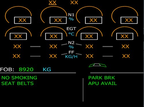

EPR または N1 は、コックピットでの推力表示器として使用されます。これは、エンジン メーカーの好みに応じて、どちらか一方が、航空機で測定されない推力の有効な代替手段となるためです。そのため、これらは推力設定パラメーターとして知られています。N1 はGeneral Electric AviationおよびCFM Internationalによって推奨され、EPR はPratt & WhitneyおよびRolls-Royceによって推奨されています。ターボジェットにおける EPR の意味は、ジェットパイプ内の圧力をエンジン外部の圧力と比較し、圧力の上昇はエンジンのポンプ作用の結果です。エンジンと追加されたノズルの組み合わせによる動作により、推力が生成されます。基本エンジン (コンプレッサー、燃焼器、タービン) の機能は、空気を周囲の空気よりも高い圧力までポンプすることです。[41]次に、ノズルと呼ばれる狭い領域を通過することで加速されます。2 つの独立したノズルを備えたバイパス エンジンの場合、それぞれの圧力はノズル領域に応じて重み付けされます。そのため、ロールスロイスRB211推力計は統合EPR(IEPR)として知られています。推力は気流を調整することで簡単に制御でき、気流はすべてファンによって送り出されるため、ゼネラル・エレクトリック・アビエーションではN1を使用して推力を設定します。[42]
EGT はコックピットの燃料流量計です。燃焼器で燃焼した燃料がタービン入口温度を決定しますが、これは確実に測定することはできないため、EGT は適切な代替手段です。エンジンが新品の状態から劣化すると、推力を生み出すためにより多くの燃料が必要になり、その結果ガスの温度が高くなります。たとえば、離陸時の EPR では、エンジンが新品の状態から劣化するにつれて、燃料流量と EGT が稼働時間とともに増加します。エンジンは徐々に燃料を消費し、部品を交換して元の低い動作温度を回復し、燃料購入コストを削減する必要があります。[43]
コックピットのパフォーマンス指標は誤解を招く可能性がある
EPRは飛行範囲を超える推力に直接関係しているが、アメリカン航空の最初のジェットエンジンであるプラット・アンド・ホイットニーJT3Cの経験では計器の問題が生じたため、コックピットの読み取り値が疑問視され、他のパラメータであるFFとN1が絶望的に飛行員によって使用された。[44]
EPR は圧力測定に基づいており、サンプルチューブは詰まりやすい。エアフロリダ 90 便は、雪と氷の状態で離陸時に墜落した。離陸に必要な推力は 14,500 ポンドで、通常は推力レバーを前進させて EPR の読み取り値が 2.04 になるように設定される。EPR プローブの氷結により、設定された値、つまり 2.04 は誤りであり、実際には 1.70 に相当し、実際の推力はわずか 10,750 ポンドであった。加速が遅いため、離陸速度に達するまでに通常より 15 秒長くかかり、墜落の原因となった。[45]
EGT の測定値も誤解を招く可能性がある。タービンから出るガスの温度は、エンジンの使用とともに部品が摩耗するにつれて上昇するが、戦略航空軍は、タービン部品が曲がったり壊れたりしていることを知らずに J57 および TF33 エンジンの飛行を承認した。彼らは、額面通りに受け取るとエンジンが許容できる状態にあることを示す低い EGT の測定値に惑わされた。EGT プローブは、エンジンの真の状態を表す代表的なガス温度をサンプリングするのに適切な位置になかったことが判明した。[46]
パフォーマンスの向上
SFC の観点から見たパフォーマンスは、重量やサイズではなく、発電所全体の総合的なエネルギー変換効率、つまり廃棄物が最小限に抑えられる程度です。発電所全体の総合的な効率は、廃棄物をすべて生成する構成部品の効率に依存します。
最初はターボジェットとして、次にターボファンとして、ジェットエンジンの性能向上は、圧力比 (PR) と部品効率の継続的な向上、圧力損失の低減、および冷却技術と相まってタービン入口温度 (TIT) の上昇を可能にした材料開発によって実現しました。また、翼面上のガス流のみが推力に寄与するため、ガス経路からの漏れも減少しました。TIT の増加は出力の増加を意味し、ターボジェットの場合、亜音速飛行には排気速度が高くなりすぎます。亜音速航空機の場合、TIT の増加によって得られる高いコア出力は、大量の空気にあまり運動エネルギーを加えない大型ファンの駆動に使用されます。[47]運動エネルギーは、推力を生み出す運動量の増加によって生じる望ましくない副産物で、残留速度損失として知られています。推進エンジニアの目的は、推力仕事ではなく、エネルギーの熱への変換または劣化を最小限に抑えることです。ピストンエンジンは、ターボチャージャーとターボコンパウンドで廃熱の一部を利用していました。一部は後方排気管からの推力に使用されていました。ジェットエンジンからの廃熱は利用できないため、空気がエンジンを通過する間に発生する量を減らすことで性能が向上します。これには、サリバンが説明したように、ダクトでのエントロピー生成による全圧の損失が含まれます。[48]
不可逆性またはエントロピー生成は、高品質の形態のエネルギーを低品質の形態に変換する際の破壊の尺度です。高い運動エネルギーを持つダクト内の流体の流れは高品質のエネルギー データであり、境界層は運動エネルギーの一部を低品質の形態の熱エネルギーに変換します。
コア出力が上昇したときにバイパスを増やす理由について、ハートマンは次のように述べている。[49]
比出力が高くなると、つまり燃料からジェットの KE への熱変換量が増えると、出口でのエネルギー損失が高くなるため、推力の生成に必要な KE が十分に活用されなくなります。
全体的な圧力比の増加
圧力比の増加は熱力学サイクルの改善であり、高圧での燃焼はエントロピー上昇が減少するため、これがブレイトンサイクルとして知られるジェットエンジンサイクルで高圧力比を追求する基本的な理由である。[50]圧力比の増加は、より多くの段を使用するか、段圧力比を増加させることによって達成できる。燃料消費に対する高圧力比の重要性は、1948年にボーイングB-52ストラトフォートレスにターボプロップの代わりにJ57(12:1)が選択された際に実証された。[51] ボーイングのそれまでのターボジェットの比燃料消費量に関する以前の経験は、ボーイングB-47ストラトジェットで使用されたゼネラルエレクトリックJ47(5.4:1)であり、これが最初にターボプロップの決定につながった。
ラジアルフローコンプレッサは初期のターボジェットエンジンに広く使用されていましたが、圧力比、SFC、比重、前面面積1平方フィートあたりの推力の点で軸流コンプレッサが持つ性能上の利点は、1950年にヘイン・コンスタントによって発表されました[52]。しかし、代替となる非常に小さな軸流ステージは損傷しやすく、ブレードの高さに比べて先端クリアランスが大きいため効率が悪いため、ラジアルフローコンプレッサは小型ターボファンの最後の高圧ステージとしては依然として最良の選択です。[53]
-
 初期のターボジェット、デ・ハビランド ゴブリン、圧力比 3.3:1 のラジアルフロー コンプレッサー、1942 年。
 -
![ここでロールスロイス・ダート・ターボプロップ機に示されている2段遠心圧縮機は、圧力比13:1のギャレットF109ターボファンジェットエンジンにも使用されていました。[54]](https://img-server.japedia.wiki/wikipedia/commons/thumb/2/2b/Gearbox_and_compressors_of_sectioned_Rolls-Royce_Dart_turboprop.jpg/500px-Gearbox_and_compressors_of_sectioned_Rolls-Royce_Dart_turboprop.jpg) ここでロールスロイス・ダート・ターボプロップ機に示されている2段遠心圧縮機は、圧力比13:1のギャレットF109ターボファンジェットエンジンにも使用されていました。 [54]
ここでロールスロイス・ダート・ターボプロップ機に示されている2段遠心圧縮機は、圧力比13:1のギャレットF109ターボファンジェットエンジンにも使用されていました。 [54] -
 初期のターボジェット、ゼネラル・エレクトリック J47、1947年。11 段コンプレッサーの圧力比は 5.4:1 です。
 -
IAE V2500ターボファン(1987年)は、ファン1台、低圧コンプレッサー4台、高圧コンプレッサー10台によって生成される総圧力比が約35:1です。2016年までにゼネラルエレクトリックGE9Xの総圧力比は60:1に達しました。[55]
-
 プラット・アンド・ホイットニー・カナダ PW500ビジネスジェット PW530 ターボファンには、バックスイープとパイプディフューザーを備えた 2 つの軸流および遠心圧縮機最終段を備えた HP 圧縮機が示されています。全体の圧力比は約 13:1 です。
 -
 Honeywell/ITEC F124ジェット トレーナー/軽戦闘機ターボファン。高バックスイープ、スプリッター ブレード、前縁スイープを備えた 4 つの軸流および遠心最終段を備えた HP コンプレッサーを搭載。3 つの軸流ファン、4 つの軸流 HP、および 1 つの遠心ファンによる全体の圧力比は 19.4:1。
.jpg/500px-Pratt_&_Whitney_Canada_PW500_(EBACE_2023).jpg)
.jpg/500px-EBACE_2019,_Le_Grand-Saconnex_(EB190665).jpg)
高い総圧力比を実現する技術
軸流圧縮機は、高速設計条件に適用可能な形状を有し、この条件では、気流がすべてのブレードにほとんどまたはまったく入射せずに接近し、流れの損失を最小限に抑える必要がある。設計点から条件が変化するとすぐに、ブレード入射角は低損失値から変化し、最終的に圧縮機は安定した状態で動作しなくなる。圧縮機が空気圧をあまり上げなくてもよい場合、たとえば 5 気圧まで上げなくてもよい場合、設計からの偏差は許容される。より大きな値の場合は、設計速度以下で圧縮機の形状を変更する可変機能を組み込む必要がある。5.4:1 PR の J47 の後に登場したエンジンには、前段の失速やフラッターの故障、後段の詰まりを防ぐために低速で動作する何らかの可変機能を必要とする、より高い PR の圧縮機があった。これらは、すべての段が同じ流れを通過できない場合に空気を放出するために開くバルブと、接近する空気の速度、ブレード速度、および空気とブレードの相対速度から構成される許容可能な速度三角形を維持するための可変角度ベーンであった。あるいは、コンプレッサーを2つの別々に回転するコンプレッサーに分割し、それぞれ圧力比が低いものにした。 [ 56] J57では全体で3.75 LP x 3.2 HP = 12:1であった。 [57]現代のエンジンでは、高圧力比を実現するために、ブリードバルブ、可変ブレード角度、分割コンプレッサーが併用されている。 1990年代のロールスロイス トレント700は、圧力比が36:1で、3つの独立したコンプレッサーローターを備えており、3列の可変ブレードと7つのブリードバルブが必要である。
当初は段数を増やして圧力比を高くする必要がありました。段数が低いためで、J79コンプレッサでは17段必要だったのが約1.16でした。[58]現代のコンプレッサは段あたりの圧力比が高くなっていますが、それでも同じ可変機能が必要です。10段で圧力比22:1のCFMインターナショナルLEAPエンジンHPコンプレッサには、可変入口ガイドベーンと4段の可変ステータベーンが必要です。エンジン全体の圧力比は、それに伴う温度によって制限されます。コンプレッサ出口温度は約900 Kが限界で、重量とコストの観点から材料の適合性によって決まります。[59]
-
プラット・アンド・ホイットニー JT3(1/4スケール)12:1 pr、分割コンプレッサーを備えた初期のジェットエンジンの例。また、2つのコンプレッサーの間から船外への始動/低速ブリードが必要で、90% N2を超えると閉じられます。[60]青く塗られたメッシュガード(半分取り外されている)が付いたブリードバルブベントが見える。
-
![ロールスロイスエイボンの初期のジェットエンジン。上部に3つのバルブ2組のうち1つ、下部に2つのバルブのうち1つがあり、始動時と低速運転時にコンプレッサーから空気を放出する。圧力比は7.45:1。また、前面には可変入口ガイドベーン用のベアリングの列が見える。[61]](https://img-server.japedia.wiki/wikipedia/commons/thumb/5/5a/Jet_engine%2C_cutaway_%2827441073466%29.jpg/500px-Jet_engine%2C_cutaway_%2827441073466%29.jpg) ロールスロイスエイボンの初期のジェットエンジン。上部に3つのバルブ2組のうち1つ、下部に2つのバルブのうち1つがあり、始動時と低速運転時にコンプレッサーから空気を放出する。圧力比は7.45:1。また、前面には可変入口ガイドベーン用のベアリングの列が見える。[61]
ロールスロイスエイボンの初期のジェットエンジン。上部に3つのバルブ2組のうち1つ、下部に2つのバルブのうち1つがあり、始動時と低速運転時にコンプレッサーから空気を放出する。圧力比は7.45:1。また、前面には可変入口ガイドベーン用のベアリングの列が見える。[61] -
 ゼネラル・エレクトリック CJ805 pr 13:1。始動時および低速運転に適したさまざまな角度の可変入口ガイドベーンと 6 段階の可変ステータの作動機構を示しています。
 -
 ゼネラルエレクトリック J79 /CJ805 コンプレッサ。コンプレッサケースの水平分割フランジと可変ステータがわずかに見え、回転、始動、低速運転のための円形の端部機能で明らかです。
 -
 J79/CJ805 フロントコンプレッサーステージ(VSV 付き) - 圧力が上昇するにつれて空気 1 ポンドあたりの体積が小さくなり、空気の通路が狭くなることを示しています。
 -
 損傷したコンプレッサーケースの写真は、可変ステーターの角度移動と、オープンとクローズという用語の意味を示しています。始動時および低速運転時にはステーターベーンが閉じており (左の写真)、高速時にはステーターベーンが開いていることがわかります。Klimov TV2-117ターボシャフトコンプレッサー (pr 6.6:1)
 -
![プラット・アンド・ホイットニー J58 コンプレッサーからのブリードが必要、pr 9:1。エンジン始動とナセルへの排気に必要な第4段ブリードドアは、上部ブリードチューブのすぐ前方に見える。マッハラム温度が高いために補正速度が低い場合、第4段バイパスブリード用の6本のうち3本がアフターバーナーに必要となる。[62]](https://img-server.japedia.wiki/wikipedia/commons/thumb/a/a5/SR-71A_at_Joe_Davies_Heritage_Airpark_-_J58_Jet_Engine._-_panoramio.jpg/500px-SR-71A_at_Joe_Davies_Heritage_Airpark_-_J58_Jet_Engine._-_panoramio.jpg) プラット・アンド・ホイットニー J58コンプレッサーからのブリードが必要、pr 9:1。エンジン始動とナセルへの排気に必要な第4段ブリードドアは、上部ブリードチューブのすぐ前方に見える。マッハラム温度が高いために補正速度が低いときに必要な第4段バイパスブリード用の6本のうち3本はアフターバーナーにブリードする。[62]
プラット・アンド・ホイットニー J58コンプレッサーからのブリードが必要、pr 9:1。エンジン始動とナセルへの排気に必要な第4段ブリードドアは、上部ブリードチューブのすぐ前方に見える。マッハラム温度が高いために補正速度が低いときに必要な第4段バイパスブリード用の6本のうち3本はアフターバーナーにブリードする。[62] -
![J58 2位置後縁フラップは、前段圧縮機ブレードのフラッター(振動)を防止するために必要な可変入口ガイドベーン機能を提供します。[63]](https://img-server.japedia.wiki/wikipedia/commons/thumb/5/56/Pratt_%26_Whitney_J58_Turbojet.jpg/500px-Pratt_%26_Whitney_J58_Turbojet.jpg) J58 2位置後縁フラップは、前段圧縮機ブレードのフラッター(振動)を防止するために必要な可変入口ガイドベーン機能を提供します。[63]
J58 2位置後縁フラップは、前段圧縮機ブレードのフラッター(振動)を防止するために必要な可変入口ガイドベーン機能を提供します。[63] -
ブリード バルブを備えた PW530 ビジネス ジェット ターボファン。高圧コンプレッサーの第 1 段ブレードの上にあります。圧縮空気をインペラ入口からバイパス ダクトに低速で送ります。
-
 可変吸気ガイドベーンは現代のエンジンで使用されています。このゼネラル・エレクトリック F414には茶色の可変後縁フラップが見えます。
 -
 CFM LEAP エンジン。最初の 4 段の高圧コンプレッサー入口ガイドベーンとステーターの作動機構を示しています。
![ロールスロイスエイボンの初期のジェットエンジン。上部に3つのバルブ2組のうち1つ、下部に2つのバルブのうち1つがあり、始動時と低速運転時にコンプレッサーから空気を放出する。圧力比は7.45:1。また、前面には可変入口ガイドベーン用のベアリングの列が見える。[61]](https://img-server.japedia.wiki/wikipedia/commons/thumb/5/5a/Jet_engine,_cutaway_(27441073466).jpg/500px-Jet_engine,_cutaway_(27441073466).jpg)

![J58 2位置後縁フラップは、前段圧縮機ブレードのフラッター(振動)を防止するために必要な可変入口ガイドベーン機能を提供します。[63]](https://img-server.japedia.wiki/wikipedia/commons/thumb/5/56/Pratt_&_Whitney_J58_Turbojet.jpg/500px-Pratt_&_Whitney_J58_Turbojet.jpg)
,_install_a_fan_module_onto_a_F414_jet_engine.jpg/500px-thumbnail.jpg)
.jpg/500px-LEAP_Engine_Mockup_(40202884051).jpg)
段圧力比の増加
ガスタービンでの空気圧縮は、空気の運動エネルギー(遠心インペラまたは軸方向列によって生成されたコンプレッサローター)の一部を一度に1段ずつ静圧に変換することによって達成されます。ほとんどの初期のジェットエンジンは、3.3:1(デ・ハビランド・ゴブリン)などの圧力比を持つ単段遠心コンプレッサを使用していました。軸流コンプレッサでは、段圧力比が非常に低かったものの(1.17:1 BMW 003)[64]、全体の圧力比を高めるために必要に応じて段を増やすことができたため、より高い圧力比が実現しました。より高度な遠心段は、軸流段の後ろの最後の高圧段として小型ターボファンで使用されています(プラット・アンド・ホイットニー・カナダPW300など)。同じ技術レベルでは、プラット・アンド・ホイットニーPW200ヘリコプターエンジンで唯一の段として使用された場合、8:1が生成されます。[65]遠心段は、羽根車と拡散羽根[66] 、または拡散管[67]で構成されており、拡散により静圧が上昇するため閉塞が少なくなると考えられています。[68]
軸流圧縮機は、回転ディフューザーと固定ディフューザーが交互に並んだ列で構成され、[69]各ペアが1段になっています。これらのディフューザーは、亜音速の流れに必要なだけ拡散しています。[70]隣接するブレードによって形成されるチャネル、拡散量は、接線に対する角度を変えることで調整されます。これはスタッガー角として知られています。[71]拡散が大きいほど圧力比は高くなりますが、圧縮機内の流れは圧力上昇に逆らうため流れの分離の影響を受けやすくなります(ガスは自然に高圧から低圧に流れます)。段圧力比は2016年までに増加し、11段で27:1(GE9X高圧圧縮機)を達成できるようになりました。[55]
低アスペクト比の圧縮機ブレードは、空気力学的にも構造的にも効率が良く、1950年代のターボジェットであるTumansky R-11で導入され、その後、1983年にGarrett TFE731-5 [ 72]、1984年にRB211-535E4 [73]、およびPratt & Whitney Canada JT15D -5 [74]で、幅広弦ファンブレードの例が導入されました。
-
1942年式デ・ハビランド・ゴブリン(圧力比3.3:1の単遠心段付き)
-
 1940年BMW 003、7段のステージ圧力比はそれぞれ1.17:1
 -
 遠心段にはディフューザー ベーンがあり、このTurbomeca Artousteエンジンに見られるように、インペラの先端から出た後の空気の流れを遅くします。このベーンは、段の圧力比に寄与します。
 -
 Klimov VK-1この写真は、典型的な遠心段のキャンバー型ディフューザーベーンを示していますが、内部空気システム用の小さな冷却インペラ上にあります。エンジンの両面遠心コンプレッサー段については、同等のものは断面では見えていません。
 -
![圧力比7:1のプラット・アンド・ホイットニー・カナダJT15Dインペラーでは、代わりに6段または7段の軸流ステージが必要であった。[75] この遠心ステージでは、ディフューザーベーンではなくパイプディフューザーが使用されている。ファンブレードは、小型ブースターブレードの前にあるファンハブには取り付けられていない。](https://img-server.japedia.wiki/wikipedia/commons/thumb/7/74/Pratt_%26_Whitney_JT15D-4_two_shaft_engine_-_Malaga_Airport_Exposition_-_October_2022_2.jpg/500px-Pratt_%26_Whitney_JT15D-4_two_shaft_engine_-_Malaga_Airport_Exposition_-_October_2022_2.jpg) 圧力比7:1のプラット・アンド・ホイットニー・カナダJT15Dインペラーでは、代わりに6段または7段の軸流ステージが必要であった。[75]この遠心ステージでは、ディフューザーベーンではなくパイプディフューザーが使用されている。ファンブレードは、小型ブースターブレードの前にあるファンハブには取り付けられていない。
圧力比7:1のプラット・アンド・ホイットニー・カナダJT15Dインペラーでは、代わりに6段または7段の軸流ステージが必要であった。[75]この遠心ステージでは、ディフューザーベーンではなくパイプディフューザーが使用されている。ファンブレードは、小型ブースターブレードの前にあるファンハブには取り付けられていない。
.jpg/500px-Strahltriebwerk_WK-1A_(505811212).jpg)
![圧力比7:1のプラット・アンド・ホイットニー・カナダJT15Dインペラーでは、代わりに6段または7段の軸流ステージが必要であった。[75] この遠心ステージでは、ディフューザーベーンではなくパイプディフューザーが使用されている。ファンブレードは、小型ブースターブレードの前にあるファンハブには取り付けられていない。](https://img-server.japedia.wiki/wikipedia/commons/thumb/7/74/Pratt_&_Whitney_JT15D-4_two_shaft_engine_-_Malaga_Airport_Exposition_-_October_2022_2.jpg/500px-Pratt_&_Whitney_JT15D-4_two_shaft_engine_-_Malaga_Airport_Exposition_-_October_2022_2.jpg)
-
 この未確認の航空機用ガスタービンには、軸流圧縮機の詳細、ローターブレードと固定ステーターで拡散が発生するブレード通路 (見えませんが、ベーンを固定する溶接部から方向がわかります) が示されています。最初の列のベーンは、水平方向に示された入口ガイドベーンです。つまり、空気は軸方向にベーンから出ます。そのすぐ後には回転するローターブレードがあり、空気は狭い範囲の低損失角度でこれに当たる必要があります。方向の見かけ上の不一致は、実際には解決されています。これは、高速で移動するブレードの軸方向速度と接線速度または周方向速度が、定義する速度三角形に追加され、ブレードに対して必要な狭い入射範囲を与えるためです。
 -
![速度三角形は、固定翼と回転翼に対する空気の速度を示すために使用されます。この図は、ブレード間の気流の拡散形状を示しています。移動ローターブレード (ループシェーペン) と固定翼 (ライドシェーペン) の出口面積 B は入口面積 A よりも大きくなっています。また、空気が前縁に当たる角度を決定する速度三角形の構造も示しています。W1 は u で移動するブレードに対する速度で、最初のローターと低損失角度で一列に並んでいます。C2 は同様に固定翼と一列に並んでいます。W3 は 2 番目のローターと一列に並んでいます。速度三角形を使用すると、移動と固定の視点を混在させることができます。たとえば、空気は後縁を離れるときにローターブレードに対して速度で移動しており、三角形はブレード速度とともに、固定翼に当たるときに正面速度に変換されます。[76]](https://img-server.japedia.wiki/wikipedia/commons/thumb/0/06/Compressor_stage.JPG/500px-Compressor_stage.JPG) 速度三角形は、固定翼と回転翼に対する空気の速度を示すために使用されます。この図は、ブレード間の気流の拡散形状を示しています。移動ローターブレード (ループシェーペン) と固定翼 (ライドシェーペン) の出口面積 B は入口面積 A よりも大きくなっています。また、空気が前縁に当たる角度を決定する速度三角形の構造も示しています。W 1は、u で移動するブレードに対する速度であり、最初のローターと低損失角度で一列に並んでいます。C 2は同様に固定翼と一列に並んでいます。W 3 は2 番目のローターと一列に並んでいます。速度三角形により、移動と静止の視点を混在させることができます。たとえば、空気は、後縁を離れるときにローターブレードに対して速度で移動しており、三角形はブレード速度とともに、固定翼に当たるときに正面速度に変換されます。[76]
速度三角形は、固定翼と回転翼に対する空気の速度を示すために使用されます。この図は、ブレード間の気流の拡散形状を示しています。移動ローターブレード (ループシェーペン) と固定翼 (ライドシェーペン) の出口面積 B は入口面積 A よりも大きくなっています。また、空気が前縁に当たる角度を決定する速度三角形の構造も示しています。W 1は、u で移動するブレードに対する速度であり、最初のローターと低損失角度で一列に並んでいます。C 2は同様に固定翼と一列に並んでいます。W 3 は2 番目のローターと一列に並んでいます。速度三角形により、移動と静止の視点を混在させることができます。たとえば、空気は、後縁を離れるときにローターブレードに対して速度で移動しており、三角形はブレード速度とともに、固定翼に当たるときに正面速度に変換されます。[76] -
 ゼネラル・エレクトリック J85ターボジェット コンプレッサー。サージ中にブレードが曲がったときにブレードが接触するのを防ぐために必要な、回転ブレードと固定ブレード間の軸方向間隔を示しています。
 -
![この図は、軸流圧縮機ローターの複雑な流れ場のいくつかの特徴を示しています。これらはエントロピーを生成する損失メカニズムです。流れは、動翼と静止翼の各列間の相対運動により不安定になります。示されている流れのパターンは二次流れとして知られており、圧縮機の損失の半分を占めています。[77]](https://img-server.japedia.wiki/wikipedia/commons/thumb/e/e9/COMBUSTOR_SECTIONS_-_NARA_-_17447547.jpg/500px-COMBUSTOR_SECTIONS_-_NARA_-_17447547.jpg) この図は、軸流圧縮機ローターの複雑な流れ場のいくつかの特徴を示しています。これらはエントロピーを生成する損失メカニズムです。流れは、動翼と静止翼の各列間の相対運動により不安定になります。示されている流れのパターンは二次流れとして知られており、圧縮機の損失の半分を占めています。[77]
この図は、軸流圧縮機ローターの複雑な流れ場のいくつかの特徴を示しています。これらはエントロピーを生成する損失メカニズムです。流れは、動翼と静止翼の各列間の相対運動により不安定になります。示されている流れのパターンは二次流れとして知られており、圧縮機の損失の半分を占めています。[77] -
 ロールスロイス エイボンの高アスペクト比 (狭い) コンプレッサーブレードは、1970 年代まで軍用エンジンで一般的でした。
 -
![1950年代のTumansky R-11低アスペクト比(幅広)ブレードは、他の軍用エンジンに導入される20年前に登場しました。[78]](https://img-server.japedia.wiki/wikipedia/commons/thumb/4/49/Strahltriebwerk_%2841509006890%29.jpg/500px-Strahltriebwerk_%2841509006890%29.jpg) 1950年代のTumansky R-11低アスペクト比(幅広)ブレードは、他の軍用エンジンに導入される20年前に導入されました。[78]
1950年代のTumansky R-11低アスペクト比(幅広)ブレードは、他の軍用エンジンに導入される20年前に導入されました。[78]
![1950年代のTumansky R-11低アスペクト比(幅広)ブレードは、他の軍用エンジンに導入される20年前に登場しました。[78]](https://img-server.japedia.wiki/wikipedia/commons/thumb/4/49/Strahltriebwerk_(41509006890).jpg/500px-Strahltriebwerk_(41509006890).jpg)
ファン効率
現代のエンジンのファンブレードは、従来の狭翼弦ブレードに代わる広い翼弦を有しており、許容できない振動を防ぐためにスナッバーまたはシュラウドが必要であった。翼弦を長くすることでブレードが十分に硬くなり、スナッバーが不要になったことで、鳥、雹、氷の侵入による損傷に対する耐性も高まり、[79]効率、サージマージン、騒音低減の改善という無関係な利点もいくつかもたらされた。[80]また、コンプレッサーの効率を低下させる翼表面の浸食を防ぐために、コンプレッサーの入口から破片を遠心分離するための軸方向距離も長くなっている。
-
 1960 年代のPratt & Whitney JT9D 92 インチ径ファンは、高アスペクト比として知られる細長いブレードを備えています。このタイプのブレードは、空気の流れが 2 次元、つまりブレードの長さに沿って質量、運動量、エネルギーが交換されない弦線に沿っていると想定して設計されました。CFD が導入されると、3 次元のブレード周りの実際の流れをモデル化するワイド弦ブレードに置き換えられました。
 -
![1970年、ギャレットTFE731は、三次元数値流体力学(CFD)の助けを借りて設計された遷音速(ブレードの外側部分の超音速相対速度)ファンの初期の例です。[81]](https://img-server.japedia.wiki/wikipedia/commons/thumb/e/e5/JET_ENGINES_-_NARA_-_17421181.jpg/500px-JET_ENGINES_-_NARA_-_17421181.jpg) 1970年、ギャレットTFE731は、三次元数値流体力学(CFD)の助けを借りて設計された遷音速(ブレードの外側部分の超音速相対速度)ファンの初期の例です。[81]
1970年、ギャレットTFE731は、三次元数値流体力学(CFD)の助けを借りて設計された遷音速(ブレードの外側部分の超音速相対速度)ファンの初期の例です。[81] -
 1967年型プラット・アンド・ホイットニーJT15D -1~-4ファンは、ファン効率を低下させる部分スパンシュラウドと局所補強材を備えている。
 -
 1984 年に導入されたPratt & Whitney JT15D -5 では、幅広の翼弦ファンブレードとシュラウド、および補強材が削除されています。
 -
![ロールスロイス トレント 900 116 インチ径ファン。ファンの外側半分は超音速の相対速度を持ち、その結果、通路に衝撃波が発生します。視覚的に明らかなのは、ハブから先端にかけて前方から後方、さらに前方へと変化するブレード前縁スイープと、ハブではほぼ軸方向から先端ではほぼ円周方向に変化するブレードツイストです。ブレードの形状により、衝撃波が先端前縁を超えて放出されるのを防ぐのに十分な距離が前縁の後ろにあります (サージとフラッターを防止)。前縁スイープとブレードツイストに寄与する各ラジアルセクションの遠心力は、回転による応力を最小限に抑えるラジアルラインに近いところに作用します。[82][83]](https://img-server.japedia.wiki/wikipedia/commons/thumb/0/07/Rolls-Royce_Trent_900_front.jpg/500px-Rolls-Royce_Trent_900_front.jpg) ロールスロイス トレント900 116 インチ径ファン。ファンの外側半分は超音速の相対速度を持ち、その結果、通路に衝撃波が発生します。視覚的に明らかなのは、ハブから先端にかけて前方から後方、さらに前方へと変化するブレード前縁スイープと、ハブではほぼ軸方向から先端ではほぼ円周方向に変化するブレードツイストです。ブレードの形状により、衝撃波が先端前縁を超えて放出されるのを防ぐのに十分な距離が前縁の後ろにあります (サージとフラッターを防止)。前縁スイープとブレードツイストに寄与する各ラジアルセクションの遠心力は、回転による応力を最小限に抑えるラジアルラインに近いところに作用します。[82] [83]
ロールスロイス トレント900 116 インチ径ファン。ファンの外側半分は超音速の相対速度を持ち、その結果、通路に衝撃波が発生します。視覚的に明らかなのは、ハブから先端にかけて前方から後方、さらに前方へと変化するブレード前縁スイープと、ハブではほぼ軸方向から先端ではほぼ円周方向に変化するブレードツイストです。ブレードの形状により、衝撃波が先端前縁を超えて放出されるのを防ぐのに十分な距離が前縁の後ろにあります (サージとフラッターを防止)。前縁スイープとブレードツイストに寄与する各ラジアルセクションの遠心力は、回転による応力を最小限に抑えるラジアルラインに近いところに作用します。[82] [83]
.jpg/500px-Aerocardal_(9321710382).jpg)

燃焼
エンジンとアフターバーナーの両方の燃焼器における熱伝達と摩擦の影響により、よどみ点圧力が失われ、エントロピーが増加します。圧力損失は T~s 線図に示され、線図の作業部分の面積が減少することがわかります。燃焼器を通る圧力損失には 2 つの要因があります。1 つは、すべての冷却穴を含むコンプレッサーからの空気が燃焼領域に流入することによるもの (摩擦圧力損失) で、空気は流れていますが燃焼は行われていません。流れるガスに熱が加わると、別の種類の圧力損失 (運動量圧力損失) が追加されます。
よどみ点圧力損失に加えて、燃焼性能のもう 1 つの尺度は不完全燃焼です。燃焼効率は、高推力レベルでは常に 100% に近く、HC と CO の量はわずかですが、アイドル運転付近では大幅な改善が必要でした。1990 年代には、スモッグや酸性雨などの原因となる窒素酸化物 (NOx) の削減に焦点が当てられました。NOx を削減するための燃焼器技術は、プラット& ホイットニーが TALON (先進低 NOx 技術) PW4098燃焼器で導入したリッチバーン、クイックミックス、リーンバーン (RQL) [84]です。[85] RQL 技術は、ロールスロイス社のフェーズ 5 トレント 1000 燃焼器やゼネラルエレクトリック社の LEC (低排出ガス燃焼器) でも使用されています。[86]
エンジンの燃焼器の構成には、逆流分離型、直通分離型、環状缶型 (これら 3 つはいずれも歴史的であり、環状のフロー チャンバーによってタービンへの面積が広がり、流れが均一になる)、および現代の環状型と逆流環状型があります。燃焼用の燃料の準備は、燃料を小さな滴に変換する (霧化) か、炎に浸したチューブ内で空気で加熱する (気化) ことによって行われます。
遠心圧縮機を備えた初期のジェット エンジンの例であるロールス ロイス ウェランドとゼネラル エレクトリック J31 は、逆流燃焼器を使用していました。遠心最終圧縮段を組み込んだより現代的な小型ジェット エンジンも逆流燃焼器を使用しており、6,000 ポンドのEclipse 500超軽量ジェット機に搭載された 1,000 lbf 推力のPratt & Whitney Canada PW600から、97,000 ポンドのBritish Aerospace 146旅客機に搭載された7,000 lbf 推力のLycoming ALF 502まで多岐にわたります。
-
![ゼネラルエレクトリックJ31には10個の逆流燃焼器が備えられている。圧縮空気は18-8ステンレス鋼の外側ケーシングと内側のインコネル製炎管の間を流れ、一連の穴を通って管の内側に流れ、そこで燃料と混合される。燃焼は全長にわたって継続し、タービンに逆方向に流れる前に完了する。[87]](https://img-server.japedia.wiki/wikipedia/commons/thumb/e/ef/General_Electric_J31NMUSAF_%28070110-F-1234S-009%29.jpg/500px-General_Electric_J31NMUSAF_%28070110-F-1234S-009%29.jpg) ゼネラルエレクトリックJ31には10個の逆流燃焼器が備えられている。圧縮空気は18-8ステンレス鋼の外側ケーシングと内側のインコネル製炎管の間を流れ、一連の穴を通って管の内側に流れ、そこで燃料と混合される。燃焼は全長にわたって継続し、タービンに逆流する前に完了する。[87]
ゼネラルエレクトリックJ31には10個の逆流燃焼器が備えられている。圧縮空気は18-8ステンレス鋼の外側ケーシングと内側のインコネル製炎管の間を流れ、一連の穴を通って管の内側に流れ、そこで燃料と混合される。燃焼は全長にわたって継続し、タービンに逆流する前に完了する。[87] -
![デ・ハビランド・ゴブリンは16個の直通燃焼室を持つ。各燃焼室は耐圧外側ケーシングに囲まれた炎管で構成されている。これらは圧力を均衡させ、始動時に2本の管から炎を伝播させる管で接続されており、点火装置のうち1つは上部の管に表示されている。[88]](https://img-server.japedia.wiki/wikipedia/commons/thumb/5/58/Royal_Military_Museum_Brussels_2007_224.JPG/500px-Royal_Military_Museum_Brussels_2007_224.JPG) デ・ハビランド・ゴブリンは16個の直通燃焼室を持つ。各燃焼室は耐圧外装に囲まれた炎管で構成されている。炎管は圧力を均衡させ、始動時に2本の炎管から炎を伝播させる管で接続されており、点火装置が1つ上部の管に表示されている。[88]
デ・ハビランド・ゴブリンは16個の直通燃焼室を持つ。各燃焼室は耐圧外装に囲まれた炎管で構成されている。炎管は圧力を均衡させ、始動時に2本の炎管から炎を伝播させる管で接続されており、点火装置が1つ上部の管に表示されている。[88] -
![ロールスロイス ニーンには9つの燃焼室がある。切り欠きは、炎点火装置が取り付けられた2つの燃焼室のうちの1つで、点火装置は高温のガス流に直接さらされるよりも涼しい場所に置かれる。始動時には、小型の自己完結型ユニット(オレンジ色のソレノイドが図示)からの霧状燃料が点火プラグによって点火され、炎を帯びた燃料の噴流がバーナーからの主燃料スプレーに噴射される。燃焼は相互接続チューブを通じてすべての燃焼室に伝播する。[89]](https://img-server.japedia.wiki/wikipedia/commons/thumb/b/b6/Combustor_on_Rolls-Royce_Nene_turbojet_%282%29.jpg/500px-Combustor_on_Rolls-Royce_Nene_turbojet_%282%29.jpg) ロールスロイス ニーンには9つの燃焼室がある。切り欠きは、炎点火装置が取り付けられた2つの燃焼室のうちの1つで、点火装置は高温のガス流に直接さらされるよりも涼しい場所に置かれる。始動時には、小型の自己完結型ユニット(オレンジ色のソレノイドが図示)からの霧状燃料が点火プラグによって点火され、炎を帯びた燃料の噴流がバーナーからの主燃料スプレーに噴射される。燃焼は相互接続チューブを通じてすべての燃焼室に伝播する。[89]
ロールスロイス ニーンには9つの燃焼室がある。切り欠きは、炎点火装置が取り付けられた2つの燃焼室のうちの1つで、点火装置は高温のガス流に直接さらされるよりも涼しい場所に置かれる。始動時には、小型の自己完結型ユニット(オレンジ色のソレノイドが図示)からの霧状燃料が点火プラグによって点火され、炎を帯びた燃料の噴流がバーナーからの主燃料スプレーに噴射される。燃焼は相互接続チューブを通じてすべての燃焼室に伝播する。[89] -
![ウェスティングハウスJ46「ウォーキングスティック」燃料気化管は環状燃焼器に取り付けられている。[90] 燃料気化はサファイア、バイパー、ペガサス、オリンパス593、RB211エンジンでも採用されている。それ以外のエンジンでは、燃料管内の燃料圧力を燃焼器内の運動エネルギーに変換し、十分に霧化されたスプレーを生成する何らかの形の霧化ノズル[91]を使用している。](https://img-server.japedia.wiki/wikipedia/commons/thumb/7/75/Westinghouse_J46-WE-8_axial_flow_jet_engine_-_Hiller_Aviation_Museum_-_San_Carlos%2C_California_-_DSC03061.jpg/500px-Westinghouse_J46-WE-8_axial_flow_jet_engine_-_Hiller_Aviation_Museum_-_San_Carlos%2C_California_-_DSC03061.jpg) ウェスティングハウスJ46「ウォーキングスティック」燃料気化管は環状燃焼器に取り付けられている。[90]燃料気化はサファイア、バイパー、ペガサス、オリンパス593、RB211エンジンでも採用されている。それ以外のエンジンでは、燃料管内の燃料圧力を燃焼器内の運動エネルギーに変換し、十分に霧化されたスプレーを生成する何らかの形の噴霧ノズル[91]を使用している。
ウェスティングハウスJ46「ウォーキングスティック」燃料気化管は環状燃焼器に取り付けられている。[90]燃料気化はサファイア、バイパー、ペガサス、オリンパス593、RB211エンジンでも採用されている。それ以外のエンジンでは、燃料管内の燃料圧力を燃焼器内の運動エネルギーに変換し、十分に霧化されたスプレーを生成する何らかの形の噴霧ノズル[91]を使用している。 -
プラット・アンド・ホイットニーJ57は8つの環状缶燃焼器を備えており、これは炎缶が独立しているが、外側と内側のケースの間の環状空間内に収まっていることを意味する。各缶は小型の環状燃焼室で、中央に空気を冷却するための管があり、その周囲に6つのバーナーが配置されている。[92]
-
-
 JT9D ストレートスルー環状燃焼器、左から右への空気の流れ。噴霧燃料ノズルはデュアルオリフィスまたはデュプレックスタイプです。プライマリまたはパイロットフローは、低速エンジンでは中央の小さな穴 (オリフィス) から左側の燃料チューブを通って流れます。セカンダリまたはメインフローは、高速ではその周囲の大きな開口部から右側のチューブを通って流れます。左側の小さなコンプレッサ出口ガイドベーンからの空気の流れは、面積が増加するディフューザーに入り、3 つの部分に分割されます。中央の流れは燃焼器に入り、燃料と混合されます。外側と内側の部分は、図の穴を通って燃焼器に徐々に入り、燃焼を完了してから希釈され、タービンに適した最終出口温度になります。
 -
![エンジンの燃焼器は、コンプレッサーから出る高速の空気を大幅に減速させる必要がある。これは、燃焼圧力損失を低く抑えるために、燃焼前に流路面積(ディフューザー)を増やして Mn を低くすることで実現する。流入する燃料の初期燃焼を起こすには、燃料ノズルの近くに再循環ゾーン(円形の空気流路で表示)を維持しなければならない。このゾーン(一次ゾーン)は、2 つの一次空気経路、燃料インジェクターの周りの旋回羽根(灰色の四角で表示)から流入する旋回流、および一次空気の放射状流入穴の最初の列によって維持される。燃焼は中間空気で完了し、ガス温度は希釈空気でタービンの長寿命に必要な値まで低下する。[93]](https://img-server.japedia.wiki/wikipedia/commons/thumb/4/49/Combustor_diagram_airflow.png/500px-Combustor_diagram_airflow.png) エンジンの燃焼器は、コンプレッサーから出る高速の空気を大幅に減速する必要がある。これは、燃焼圧力損失を低く抑えるために、燃焼前に流路面積(ディフューザー)を増やして Mn を低くすることで実現する。流入する燃料の初期燃焼を起こすには、燃料ノズルの近くに再循環ゾーン(円形の空気流路で表示)を維持しなければならない。このゾーン(一次ゾーン)は、2 つの一次空気経路、燃料インジェクターの周りの旋回羽根(灰色の四角で表示)から流入する旋回流、および一次空気の放射状流入穴の最初の列によって維持される。燃焼は中間空気で完了し、ガス温度は希釈空気でタービンの長寿命に必要な値まで低下する。[93]
エンジンの燃焼器は、コンプレッサーから出る高速の空気を大幅に減速する必要がある。これは、燃焼圧力損失を低く抑えるために、燃焼前に流路面積(ディフューザー)を増やして Mn を低くすることで実現する。流入する燃料の初期燃焼を起こすには、燃料ノズルの近くに再循環ゾーン(円形の空気流路で表示)を維持しなければならない。このゾーン(一次ゾーン)は、2 つの一次空気経路、燃料インジェクターの周りの旋回羽根(灰色の四角で表示)から流入する旋回流、および一次空気の放射状流入穴の最初の列によって維持される。燃焼は中間空気で完了し、ガス温度は希釈空気でタービンの長寿命に必要な値まで低下する。[93] -
 J85 環状燃焼器、後端を上にして表示。エンジンに取り付けられると、この開いた端は第 1 段タービン ノズル ベーン リングによって閉じられ、そのフロー領域 (排気ノズルの領域と合わせて) がコンプレッサーに逆圧をかけ、コンプレッサー マップに示されているように圧力上昇と流量を制御します。
 -
![ロールスロイス ターボメカ アドゥール軍用ターボファン。エントロピー生成を最小限に抑えるためには、燃焼器の圧力損失を可能な限り減らすのではなく、一定の最小圧力を維持する必要がある。高圧コンプレッサーからの冷却空気が流れるためにはタービンでの圧力を下げる必要があるため、タービン冷却回路での逆流を防ぐために圧力を維持する必要がある。[94][95] コンプレッサー(青)からの冷却空気は、タービン領域(オレンジ色に塗られたノズルガイドベーン)に流れなければならない。これは、燃焼器内で発生する圧力低下によって可能になる。また、空気を減速するために必要なコンプレッサーから燃焼器への領域の増加も明らかである。](https://img-server.japedia.wiki/wikipedia/commons/thumb/8/80/Core_section_of_a_sectioned_Rolls-Royce_Turbom%C3%A9ca_Adour_turbofan.jpg/500px-Core_section_of_a_sectioned_Rolls-Royce_Turbom%C3%A9ca_Adour_turbofan.jpg) ロールスロイス ターボメカ アドゥール軍用ターボファン。エントロピー生成を最小限に抑えるためには、燃焼器の圧力損失を可能な限り減らすのではなく、ある一定の最小圧力損失を維持する必要がある。高圧コンプレッサーからの冷却空気が流れるためにはタービンでの圧力を下げる必要があるため、タービン冷却回路での逆流を防ぐために圧力を維持しなければならない。[94] [95]コンプレッサー(青)からの冷却空気はタービン領域(オレンジ色に塗られたノズルガイドベーン)に流れなければならない。これは、燃焼器内で発生する圧力低下によって可能になる。また、空気を減速するために必要なコンプレッサーから燃焼器への面積の増加も明らかである。
ロールスロイス ターボメカ アドゥール軍用ターボファン。エントロピー生成を最小限に抑えるためには、燃焼器の圧力損失を可能な限り減らすのではなく、ある一定の最小圧力損失を維持する必要がある。高圧コンプレッサーからの冷却空気が流れるためにはタービンでの圧力を下げる必要があるため、タービン冷却回路での逆流を防ぐために圧力を維持しなければならない。[94] [95]コンプレッサー(青)からの冷却空気はタービン領域(オレンジ色に塗られたノズルガイドベーン)に流れなければならない。これは、燃焼器内で発生する圧力低下によって可能になる。また、空気を減速するために必要なコンプレッサーから燃焼器への面積の増加も明らかである。
![ゼネラルエレクトリックJ31には10個の逆流燃焼器が備えられている。圧縮空気は18-8ステンレス鋼の外側ケーシングと内側のインコネル製炎管の間を流れ、一連の穴を通って管の内側に流れ、そこで燃料と混合される。燃焼は全長にわたって継続し、タービンに逆方向に流れる前に完了する。[87]](https://img-server.japedia.wiki/wikipedia/commons/thumb/e/ef/General_Electric_J31NMUSAF_(070110-F-1234S-009).jpg/500px-General_Electric_J31NMUSAF_(070110-F-1234S-009).jpg)
![ロールスロイス ニーンには9つの燃焼室がある。切り欠きは、炎点火装置が取り付けられた2つの燃焼室のうちの1つで、点火装置は高温のガス流に直接さらされるよりも涼しい場所に置かれる。始動時には、小型の自己完結型ユニット(オレンジ色のソレノイドが図示)からの霧状燃料が点火プラグによって点火され、炎を帯びた燃料の噴流がバーナーからの主燃料スプレーに噴射される。燃焼は相互接続チューブを通じてすべての燃焼室に伝播する。[89]](https://img-server.japedia.wiki/wikipedia/commons/thumb/b/b6/Combustor_on_Rolls-Royce_Nene_turbojet_(2).jpg/500px-Combustor_on_Rolls-Royce_Nene_turbojet_(2).jpg)
![ウェスティングハウスJ46「ウォーキングスティック」燃料気化管は環状燃焼器に取り付けられている。[90] 燃料気化はサファイア、バイパー、ペガサス、オリンパス593、RB211エンジンでも採用されている。それ以外のエンジンでは、燃料管内の燃料圧力を燃焼器内の運動エネルギーに変換し、十分に霧化されたスプレーを生成する何らかの形の霧化ノズル[91]を使用している。](https://img-server.japedia.wiki/wikipedia/commons/thumb/7/75/Westinghouse_J46-WE-8_axial_flow_jet_engine_-_Hiller_Aviation_Museum_-_San_Carlos,_California_-_DSC03061.jpg/500px-Westinghouse_J46-WE-8_axial_flow_jet_engine_-_Hiller_Aviation_Museum_-_San_Carlos,_California_-_DSC03061.jpg)

アフターバーニングに関する初期のテストでは、燃焼ゾーンへの入口でのマッハ数が0.3を超えると、燃焼による圧力損失が急速に増加することが示されました。これはタービンを出るMnよりも低いため、燃焼が始まり、再循環ゾーンで維持される炎保持器の前でガスを減速するための拡散セクションが必要です。[96]アフターバーナーのテストで当初驚いたのは、燃料が熱いタービン排気中で自然に点火しないということでした。そのため、アフターバーナーではさまざまな点火方法が使用されています。炎が始まる場所でのMnが十分に低く(0.2~0.25 EJ200 [97])、燃焼ゾーンのダクト径が十分に大きいことが、アフターバーナーでの全圧損失を許容できる低いレベルに抑えるために必要です。エンジンの燃焼器と同様に、ディフューザーから始めて、前のコンポーネントからの空気を減速する必要があります。エンジン燃焼器内の炎の安定化は、気流のみを使用して達成され、例えば、燃料インジェクターの周りの渦流羽根とライナーの穴から入る空気とを組み合わせて流れを逆転させます。アフターバーナーは、ブラフボディフレームホルダー(「V」字型ガッター)と呼ばれる流れの障害物を使用します。アフターバーナーの燃料ノズルは燃焼ゾーンの上流に配置されており、霧状燃料がタービン排気と十分に混合して炎がフレームホルダーからダクト全体に広がるようにします。
すべてのダクトにはダクト壁の摩擦による圧力損失がありますが、アフターバーナーには火炎保持器と燃料供給管による追加の損失があります。燃焼による基本的な圧力損失は、燃焼ゾーンへの入口でのMnと、アフターバーナー内の温度上昇による燃焼燃料の量とともに増加します。[98]
アフターバーナーの温度を制限するタービンはないが、ダクトライナーと可変ノズルにはエンジン流入気流の約10%の冷却空気が必要である。この空気中の酸素は燃焼には利用できない。[99]
-
 Tumansky R-11ターボジェット アフターバーナー フレア (拡散セクション) は、燃焼前に Mn の流量を減らすために必要です。フレアは、目に見えるフレームホルダーのすぐ後ろで終わります。燃焼セクションと出口ノズルがありません。
 -
 ロールスロイス ターボメカ アドゥール ターボファン アフターバーナーには、4 つの同心円状のブラフボディ フレームホルダー、燃料供給チューブ、2 つの触媒点火装置が示されています。これらはすべてガスの流れを妨害し、追加された乱流による摩擦と流れの分離によって全圧の損失を引き起こします。アフターバーナーの外側には、4 つのノズル操作ラムのうちの 1 つから 8 つのノズル操作リンクのうちの 2 つも示されています。
 -
 ガスの流路とほぼ一直線上にあるこの図には、アフターバーナー内の全圧力損失の一部の原因となる障害物がすべて示されています。下流、つまりフレームホルダーの向こう側には、熱が加わると圧力損失が発生するダクトの燃焼長さがあります。
 -
![アドゥールアフターバーナーの背面図。最小ブーストに必要な燃料を供給する4つの同心円状の蒸気ガター(火炎保持器)が見える。フルブースト用の燃料の大部分(充填燃料と呼ばれる)は、ガターの上流にある4つの同心円状のマニホールドから供給され、ダクト表面に沿った冷却空気を除いてアフターバーナー全体に炎を発生させる。また、過熱による損傷を引き起こす可能性のある圧力変動を防ぐためのアンチスクリーチライナーも見える。[100]](https://img-server.japedia.wiki/wikipedia/commons/thumb/8/8a/Rear_view_of_afterburner_in_sectioned_Rolls-Royce_Turbom%C3%A9ca_Adour_turbofan.jpg/500px-Rear_view_of_afterburner_in_sectioned_Rolls-Royce_Turbom%C3%A9ca_Adour_turbofan.jpg) アドゥールアフターバーナーの背面図。最小ブーストに必要な燃料を供給する4つの同心円状の蒸気ガター(火炎保持器)が見える。フルブースト用の燃料の大部分(充填燃料と呼ばれる)は、ガターの上流にある4つの同心円状のマニホールドから供給され、ダクト表面に沿った冷却空気を除いてアフターバーナー全体に炎を発生させる。また、過熱による損傷を引き起こす可能性のある圧力変動を防ぐためのアンチスクリーチライナーも見える。[100]
アドゥールアフターバーナーの背面図。最小ブーストに必要な燃料を供給する4つの同心円状の蒸気ガター(火炎保持器)が見える。フルブースト用の燃料の大部分(充填燃料と呼ばれる)は、ガターの上流にある4つの同心円状のマニホールドから供給され、ダクト表面に沿った冷却空気を除いてアフターバーナー全体に炎を発生させる。また、過熱による損傷を引き起こす可能性のある圧力変動を防ぐためのアンチスクリーチライナーも見える。[100] -
 Adour アフターバーナーのノズル面積操作リンクと可変ノズルが「アフターバーニングなし」または閉じた位置にある状態を示しています。アフターバーナーが作動しても、面積が拡大されて体積が増加した高温のガスが逃げるため、エンジンを通る空気の質量流量は変化しません。
 -
 Adour ノズルをアフターバーニングまたはオープン位置にします。
.jpg/500px-Afterburner_of_sectioned_Rolls-Royce_Turbom%C3%A9ca_Adour_turbofan_(2).jpg)
.jpg/500px-Afterburner_of_sectioned_Rolls-Royce_Turbom%C3%A9ca_Adour_turbofan_(3).jpg)


ダクト内の圧力損失の低減
エンジンを通過する空気は、音速程度の高速化が必要な 2 つのコンポーネントを通過します。これらは、作業が行われるコンポーネント、つまりコンプレッサーとタービンです。残りのすべてのコンポーネントでは作業が行われず、圧力損失を減らすにはマッハ数を低くする必要があります。これらのコンポーネントとは、エンジンの燃焼器とアフターバーナー、およびタービンと推進ノズルの間の排気管などのコンポーネント間の接続ダクトです。
発電所の最初のダクトは入口であり、エンジン前の全圧損失は推力生成に2回現れるため特に重要です。推力は質量流量に比例し、質量流量は全圧に比例します。ジェットノズル圧力、したがって推力もエンジン入口の全圧に比例します。[101]亜音速入口では、全圧損失はダクト通路壁に沿った摩擦によるものだけです。超音速入口では衝撃波損失も存在するため、超音速Mnの増加に伴う圧力損失を最小限に抑えるには衝撃波システムが必要です。流れが遅くなるにつれて境界層が成長し、全圧の損失がさらに増加します。衝撃による剥離や過剰な損失を防ぐため、終端衝撃波の位置の前に境界層を除去する必要があります。
-
 デ・ハビランド ゴーストエンジン。燃焼室につながる 90 度の曲がり部分には、圧力損失を減らすための回転羽根が見られます。
 -
![クリモフ VK-1 初期の亜音速吸気口。湾曲した回転羽根が吸気をインペラの前後の目へと導く。この性能向上は、1939 年にフランク・ホイットルがパワージェット W.1A に導入し、「空気がコーナーを曲がるのを助ける」というものでした。[102] ロールスロイス ニーンの同等の羽根は吸気損失を減らし、同じタービン温度で推力が 4,000 ポンドから 5,000 ポンドに増加しました。[103]](https://img-server.japedia.wiki/wikipedia/commons/thumb/c/c5/Strahltriebwerk_WK-1A.jpg/500px-Strahltriebwerk_WK-1A.jpg) クリモフ VK-1初期の亜音速吸気口。湾曲した回転羽根が吸気をインペラの前後の目へと導く。この性能向上策は、1939 年にフランク・ホイットルがパワージェット W.1 A に導入し、「空気がコーナーを曲がるのを助ける」というものだった。[102]ロールスロイス ニーンの同等の羽根は吸気損失を減らし、同じタービン温度で推力が 4,000 ポンドから 5,000 ポンドに増加した。[103]
クリモフ VK-1初期の亜音速吸気口。湾曲した回転羽根が吸気をインペラの前後の目へと導く。この性能向上策は、1939 年にフランク・ホイットルがパワージェット W.1 A に導入し、「空気がコーナーを曲がるのを助ける」というものだった。[102]ロールスロイス ニーンの同等の羽根は吸気損失を減らし、同じタービン温度で推力が 4,000 ポンドから 5,000 ポンドに増加した。[103] -
 地上での横風による境界層の分離や離陸回転中の高迎え角を防ぐ丸い吸気口リップを備えた最新の亜音速吸気口。
 -
 この写真は、ナセル入口の下縁が十分に丸みを帯びている必要がある離陸時の航空機の姿勢を示しています。
.jpg/500px-2012-10-29_12-00-17_Pentax_JH_(49290069977).jpg)
-
 コンベア B-58 ハスラー初期のマッハ 2 超音速インレットには、飛行範囲 Mn にわたって総圧力損失を減らすために、異なる軸方向位置 (移動距離 5 インチ) を持つ中央 (移動) コーンが付いています。超音速では、コーンの先端からの斜めの衝撃波と通常の衝撃波が形成されます。
 -
 Mn による損失の増加は、ショック (urti) が増えるにつれて軽減されます。
 -
![SR71 マッハ 3.2 の混合外部・内部空気入口の入口を、エンジンへの気流の方向から見た図。中央の移動コーンは、最大 M1.6 (図示) まで伸長し、M3.2 で完全に収縮するまで 26 インチ移動します。コーンの先端からの斜め衝撃、カウルの縁からの内部斜め衝撃、および法線衝撃[104] により、M3.2 で必要な圧力回復が得られます。コーンとカウルの内面の境界層は、流れが亜音速になる最終衝撃波の前に除去する必要があります。そうしないと、衝撃による剥離が発生します。2 つの除去機能が見えています。コーンの境界層は、穴の帯 (多孔質ブリード) を通じて除去されます。カウルの内面の境界層は、ショック トラップ[105] ブリードを通じて除去されます。このラムブリードは、拡散速度を低下させる「マウス」と呼ばれる流線型の塊の列の前の下部表面にわずかに見えます。[106]](https://img-server.japedia.wiki/wikipedia/commons/thumb/f/fe/Vasters_1602_%286586637283%29.jpg/500px-Vasters_1602_%286586637283%29.jpg) SR71 マッハ 3.2 混合外部内部吸気口の入口を、エンジンへの気流の方向から見た図。中央の移動コーンは、最大 M1.6 (図) まで伸び、M3.2 で完全に収縮するまで 26 インチ移動します。コーンの先端からの斜め衝撃、カウルの縁からの内部斜め衝撃、および通常の衝撃[104]により、M3.2 で必要な圧力回復が得られます。コーンとカウルの内面の境界層は、流れが亜音速になる最終衝撃波の前に除去する必要があります。そうしないと、衝撃による剥離が発生します。2 つの除去機能が目視できます。コーンの境界層は、穴の帯 (多孔質ブリード) を通じて除去されます。カウルの内面の境界層は、ショック トラップ[105]ブリードを通じて除去されます。このラム ブリードは、拡散率を下げる「マウス」と呼ばれる流線型の塊の列の前の下部表面に目視できます。[106]
SR71 マッハ 3.2 混合外部内部吸気口の入口を、エンジンへの気流の方向から見た図。中央の移動コーンは、最大 M1.6 (図) まで伸び、M3.2 で完全に収縮するまで 26 インチ移動します。コーンの先端からの斜め衝撃、カウルの縁からの内部斜め衝撃、および通常の衝撃[104]により、M3.2 で必要な圧力回復が得られます。コーンとカウルの内面の境界層は、流れが亜音速になる最終衝撃波の前に除去する必要があります。そうしないと、衝撃による剥離が発生します。2 つの除去機能が目視できます。コーンの境界層は、穴の帯 (多孔質ブリード) を通じて除去されます。カウルの内面の境界層は、ショック トラップ[105]ブリードを通じて除去されます。このラム ブリードは、拡散率を下げる「マウス」と呼ばれる流線型の塊の列の前の下部表面に目視できます。[106] -
 ロッキード SR-71 ブラックバードで使用されている、混合外部/内部吸気口の衝撃波。右の画像は、最小の圧力損失で正しく作動している吸気口を示しています。衝撃波は 2 つあり、最初の衝撃波は円錐の先端で発生して目視でき、2 番目の衝撃波は流れが超音速から亜音速に減速することで発生しますが、吸気口の内部にあるため目視できません。ダクト内部で超音速拡散が発生するため、この吸気口は外部/内部または混合圧縮吸気口と呼ばれます。左の画像は、内部の終端衝撃波が吸気口から押し出されたため、総圧力が過剰に低下して作動している吸気口を示しています。
_(2).jpg/500px-B-58_Hustler_(6693464445)_(2).jpg)
![SR71 マッハ 3.2 の混合外部・内部空気入口の入口を、エンジンへの気流の方向から見た図。中央の移動コーンは、最大 M1.6 (図示) まで伸長し、M3.2 で完全に収縮するまで 26 インチ移動します。コーンの先端からの斜め衝撃、カウルの縁からの内部斜め衝撃、および法線衝撃[104] により、M3.2 で必要な圧力回復が得られます。コーンとカウルの内面の境界層は、流れが亜音速になる最終衝撃波の前に除去する必要があります。そうしないと、衝撃による剥離が発生します。2 つの除去機能が見えています。コーンの境界層は、穴の帯 (多孔質ブリード) を通じて除去されます。カウルの内面の境界層は、ショック トラップ[105] ブリードを通じて除去されます。このラムブリードは、拡散速度を低下させる「マウス」と呼ばれる流線型の塊の列の前の下部表面にわずかに見えます。[106]](https://img-server.japedia.wiki/wikipedia/commons/thumb/f/fe/Vasters_1602_(6586637283).jpg/500px-Vasters_1602_(6586637283).jpg)
Flow through bypass ducts is subject to frictional losses and obstructions causing flow separation. Care has to be taken to avoid steps and gaps which increase flow losses as does their presence on aircraft surfaces where they cause drag.[107] Ducts need internal streamlining in the same way as external surfaces. Tubes have to cross the duct bringing compressed air from the gas generator to the aircraft pylon for its ECS. The tubes creates turbulent wakes in the bypass air which shows up as a pressure loss, an increase in entropy. A streamlined fairing round the tube is a performance improvement, it reduces the rise in entropy. The higher the flow Mn the greater the pressure loss.[108]
-
 Pratt & Whitney TF30. Early military bypass engine showing two bleed air tubes obstructing airflow in bypass duct
 -
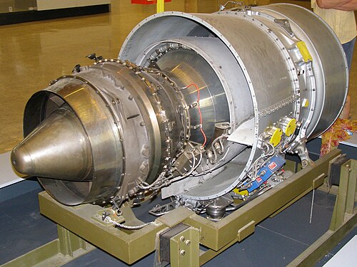 Pratt & Whitney Canada PW500 PW305 business jet turbofan showing fairing around bleed air tubes to reduce bypass duct pressure loss
 -
 Rolls-Royce Spey early civil bypass engine. White fuel tubes, one for each flame can, only 3 shown, have cast streamlined outer profile where they cross the bypass airflow.
 -
 Airbus A380 engine. The smooth bypass duct interior minimizes flow losses. Gaps have to be filled with grey sealer and misalignment of parts is also evident.

In constant area ducts (jetpipe) and constant area ducts with heat addition (engine combustor and afterburner) the gas accelerates due to heating up with wall friction (duct), obstructions (flame tube, flameholders and fuel manifolds), and heat addition. It accelerates subsonically, with increasing pressure loss, towards the speed of sound. To keep the pressure loss to an acceptable value the flow entering the duct is slowed down using an increase in flow area.
-
![グロスターE28/39に最初に搭載されたパワージェットW.2は、タービン出口Mnが0.8の拡散なしでテストされました。タービンブレードの環状領域は、航空機の尾部に到達するのに必要なパイプの長さに使用されました。排気は低推力で音速に達しましたが、過度の圧力損失と摩擦熱によりタービンの温度限界に達しました。パイプ入口マッハ数を減らすために、タービンの後ろに拡散が追加されました。[109]](https://img-server.japedia.wiki/wikipedia/commons/thumb/e/ea/Power_jets_W.2.jpg/500px-Power_jets_W.2.jpg) Power Jets W.2 for its initial installation in the Gloster E28/39 was tested with no diffusion from the turbine exit Mn of 0.8. The turbine blade annulus area was used for the length of pipe necessary to reach the tail of the aircraft. The exhaust reached the speed of sound at a low thrust but at the turbine temperature limit due to the excessive pressure loss and frictional heating. Diffusion was added behind the turbine with the cone shown to reduce the pipe entry Mach number.[109]
Power Jets W.2 for its initial installation in the Gloster E28/39 was tested with no diffusion from the turbine exit Mn of 0.8. The turbine blade annulus area was used for the length of pipe necessary to reach the tail of the aircraft. The exhaust reached the speed of sound at a low thrust but at the turbine temperature limit due to the excessive pressure loss and frictional heating. Diffusion was added behind the turbine with the cone shown to reduce the pipe entry Mach number.[109] -
Turbojet with afterburner. The exhaust has to be at a low enough Mn before heat addition to prevent excessive pressure loss. A diffuser is added to reduce the Mn at the beginning of the combustion zone. The afterburner then converges to match the nozzle size.
Leakage control
The jet engine has many sealing locations, more than fifty in a large engine. The cumulative effect of leakage on fuel consumption can be significant. Gas path sealing affects engine efficiency and became increasingly more important as higher pressure compressors were introduced.[110]
There are unwanted leaks from the primary gas path and necessary bleeds from the compressor which enter the secondary or internal flow system. They are all controlled by seals with design clearances. When seals rub and wear, opening up clearances, there is performance deterioration (increased fuel consumption).
Sealing of the stators was initially accomplished using knife-edge fins on the rotating part and a smooth surface for the stator shroud. Examples are the Avon and Tumansky R-11. With the invention of the honeycomb seal the labyrinth seal has an abrazive honeycomb shroud which is easily cut by the rotating seal teeth without overheating and damaging them.[111] Labyrinth seals are also used in the secondary air system between rotating and stationary parts. Example locations for these are shown by Bobo.[112] Tip clearance between compressor and turbine blades[113] and their cases is a significant source of performance loss. Much of the loss in compressors is associated with tip clearance flow.[114] For a CFM56 engine an increase in high pressure turbine tip clearance of 0.25 mm causes the engine to run 10 °C hotter (reduced efficiency) to attain take off thrust.[115] Tip clearances have to be big enough to prevent rubbing when they tend to close up during carcase bending, case distortion from thrust transfer, centre-line closure when the compressor case shrinks onto the rotor diameter( rapid reduction in temperature of air entering the engine), thrust setting changes (controlled by Active Clearance Control using compressor rotor cooling and turbine case cooling).
-
Tumansky R-11 shrouded vane interstage labyrinth, (knife/teeth) on rotor, seal visible between LP stage 2 and 3[116]
-
Pratt & Whitney TF30. Early military bypass engine showing compressor discharge six-fin labyrinth seal [117]
-
![Turbomeca Marboré IV engine showing location of leakage between impeller blades and stationary shroud, shown sectioned and painted blue. This is the leak path for a centrifugal impeller equivalent to an axial blade tip to casing clearance.[118]](https://img-server.japedia.wiki/wikipedia/commons/thumb/8/88/Marbore_IV.jpg/500px-Marbore_IV.jpg) Turbomeca Marboré IV engine showing location of leakage between impeller blades and stationary shroud, shown sectioned and painted blue. This is the leak path for a centrifugal impeller equivalent to an axial blade tip to casing clearance.[118]
Turbomeca Marboré IV engine showing location of leakage between impeller blades and stationary shroud, shown sectioned and painted blue. This is the leak path for a centrifugal impeller equivalent to an axial blade tip to casing clearance.[118] -
 EJ200 fan showing clearance between blade tips and abradable shroud.
 -
![Turbine blades with sealing shroud at tip with knife edge fins which are part of the labyrinth sealing arrangement with open honeycomb shrouds on the turbine casing.[119] The platforms at the base of the airfoil stops hot gas leakage which would overheat the turbine discs.](https://img-server.japedia.wiki/wikipedia/commons/thumb/c/ce/2013-09-18_TrentTurbineBlades.jpg/500px-2013-09-18_TrentTurbineBlades.jpg) Turbine blades with sealing shroud at tip with knife edge fins which are part of the labyrinth sealing arrangement with open honeycomb shrouds on the turbine casing.[119] The platforms at the base of the airfoil stops hot gas leakage which would overheat the turbine discs.
Turbine blades with sealing shroud at tip with knife edge fins which are part of the labyrinth sealing arrangement with open honeycomb shrouds on the turbine casing.[119] The platforms at the base of the airfoil stops hot gas leakage which would overheat the turbine discs.
Tip clearance changes with thrust changes
An engine is designed to run steady state at design points such as take-off, climb, and cruise with running clearances which minimize fuel use. Steady state means being at a constant rpm for long enough (several minutes) for all parts to have stopped moving relative to each other from transient thermal growths. During this time clearances between parts may close up to rubbing contact and wear to give larger clearances, and fuel consumption, at the important stabilized condition. This scenario inside the engine is prevented by internal compressor bore cooling[120] and external turbine casing cooling on big fan engines (active clearance control). [121][122][123]
-
![This rear view of a Klimov VK-1 turbojet shows the parts responsible for turbine temperature overshoot after increasing thrust from idle to take-off, known as transient EGT overshoot.[124] Visible is the turbine blade tip clearance which is a leakage path for gas which doesn't contribute to the power developed by the turbine. Increased gap, and leakage, means more fuel, indicated by a higher EGT, is required to get take-off thrust. Clearance is increased temporarily every time the engine goes from idle to take-off because the light casing expands quickly to the turbine gas temperature but the heavy turbine rotor takes minutes to expand to its hot diameter.](https://img-server.japedia.wiki/wikipedia/commons/thumb/a/ac/WSK_Lis-5_PM_MWB_02.jpg/500px-WSK_Lis-5_PM_MWB_02.jpg) This rear view of a Klimov VK-1 turbojet shows the parts responsible for turbine temperature overshoot after increasing thrust from idle to take-off, known as transient EGT overshoot.[124] Visible is the turbine blade tip clearance which is a leakage path for gas which doesn't contribute to the power developed by the turbine. Increased gap, and leakage, means more fuel, indicated by a higher EGT, is required to get take-off thrust. Clearance is increased temporarily every time the engine goes from idle to take-off because the light casing expands quickly to the turbine gas temperature but the heavy turbine rotor takes minutes to expand to its hot diameter.
This rear view of a Klimov VK-1 turbojet shows the parts responsible for turbine temperature overshoot after increasing thrust from idle to take-off, known as transient EGT overshoot.[124] Visible is the turbine blade tip clearance which is a leakage path for gas which doesn't contribute to the power developed by the turbine. Increased gap, and leakage, means more fuel, indicated by a higher EGT, is required to get take-off thrust. Clearance is increased temporarily every time the engine goes from idle to take-off because the light casing expands quickly to the turbine gas temperature but the heavy turbine rotor takes minutes to expand to its hot diameter. -
![This view shows the way turbine blade tip clearance is controlled actively (passive control is by material selection and internal air system cooling) using cooling-air tubes (for low pressure turbine blade tip to shroud clearance control) which circle the iridescent turbine casing on a CFM International CFM56. Cooling air manifold (smooth flat surface), to left of LPTCC tubes, for high pressure turbine blade tip clearance control.[125] Active control comes from activation of valves which supply cooling air to the tubes at appropriate flight conditions.](https://img-server.japedia.wiki/wikipedia/commons/thumb/6/6e/CFM_International_CFM56-7B26_fitted_to_Qantas_%28VH-VZY%29_Boeing_737-838_%28WL%29_at_the_Canberra_Airport_open_day_%285%29.jpg/500px-CFM_International_CFM56-7B26_fitted_to_Qantas_%28VH-VZY%29_Boeing_737-838_%28WL%29_at_the_Canberra_Airport_open_day_%285%29.jpg) This view shows the way turbine blade tip clearance is controlled actively (passive control is by material selection and internal air system cooling) using cooling-air tubes (for low pressure turbine blade tip to shroud clearance control) which circle the iridescent turbine casing on a CFM International CFM56. Cooling air manifold (smooth flat surface), to left of LPTCC tubes, for high pressure turbine blade tip clearance control.[125] Active control comes from activation of valves which supply cooling air to the tubes at appropriate flight conditions.
This view shows the way turbine blade tip clearance is controlled actively (passive control is by material selection and internal air system cooling) using cooling-air tubes (for low pressure turbine blade tip to shroud clearance control) which circle the iridescent turbine casing on a CFM International CFM56. Cooling air manifold (smooth flat surface), to left of LPTCC tubes, for high pressure turbine blade tip clearance control.[125] Active control comes from activation of valves which supply cooling air to the tubes at appropriate flight conditions.
![This view shows the way turbine blade tip clearance is controlled actively (passive control is by material selection and internal air system cooling) using cooling-air tubes (for low pressure turbine blade tip to shroud clearance control) which circle the iridescent turbine casing on a CFM International CFM56. Cooling air manifold (smooth flat surface), to left of LPTCC tubes, for high pressure turbine blade tip clearance control.[125] Active control comes from activation of valves which supply cooling air to the tubes at appropriate flight conditions.](https://img-server.japedia.wiki/wikipedia/commons/thumb/6/6e/CFM_International_CFM56-7B26_fitted_to_Qantas_(VH-VZY)_Boeing_737-838_(WL)_at_the_Canberra_Airport_open_day_(5).jpg/500px-CFM_International_CFM56-7B26_fitted_to_Qantas_(VH-VZY)_Boeing_737-838_(WL)_at_the_Canberra_Airport_open_day_(5).jpg)
Sealing at blade tips and stator shrouds
In the late 1940s it was considered by most US engine manufacturers that the optimum pr was 6:1 in light of the amount of leakage flow expected with the then-current sealing knowledge. P&W considered 12:1 could be achieved[126] but during pre-J57 development testing a compressor with 8:1 was tested and the leakage was so high that no useful work would have been produced.[127] One benefit of the subsequent wasp waist was reduced leakage from the reduced sealing diameter. In 1954 a GE engineer invented a very effective sealing scheme, the honeycomb seal[128] which reduces substantially the rubbing contact area and temperatures generated. The rotating part cuts into the cellular structure without being permanently damaged. It is widely used today. The primary gas flow through the compressor and turbine has to follow the airfoil surfaces to exchange energy with the turbomachinery. Any flow leaking past the blade tips generates entropy and reduces the efficiency of the compressor and turbine. Interlocking shrouds are present on the tips of low pressure turbine blades to provide an outer band to the flowpath which reduces tip leakage. Leakage is further reduced with the addition of seal teeth on the outer periphery of the shrouds which rub into open cell honeycomb shrouds.
-
Avon compressor shrouded vane interstage seals with labyrinth teeth on rotor
-
 LPT blade interlocking tip shrouds with seal teeth which rub into open-cell honeycomb shrouds
 -
 v2500 compressor showing seal teeth between blade rows.
 -
 Open-cell honeycomb on the shrouds at the stator/compressor drum interface showing grooves cut by mating seal teeth on rotating drum.
 -
 TFE 731 geared turbofan abradable locations in compressor and turbines
 -
 CFM International CFM56-2 shows fan tip shrouds which prevent circulation of air around the blade ends.
.jpg/500px-CFM56-2_-_Mus%C3%A9e_Safran_(cropped).jpg)
Tip clearance with backbone bending and case out-of-roundness
The advent of the high bypass civil engines, JT9D and CF6, showed the importance of thrust take off locations on the engine cases. Also, large engines have relatively flexible cases inherent in large diameter flight-weight structures giving relatively large relative displacements between heavy stiff rotors and the flexible cases.[129] Case distortion with subsequent blade tip rubbing and performance loss appeared on the JT9D installation in the Boeing 747 as a result of thrust being taken from a single point on top of the engine exhaust case. Thrust from the rear mount plane was a Boeing requirement.[130] Compared to the 15,000 lb thrust JT3D with its four structural cases the 40,000 lb thrust JT9D made economical use of supporting structure with only three structural cases making a compact lightweight design.[131] During flight testing the engines suffered violent surges and loss in performance[132] which were traced to bending of the engine backbone by 0.043 in. at the combustor case and the turbine case going out-of-round which in turn caused blade tip rubs and increased tip clearance.[133]
The three big fan engines introduced in the 1960s for wide-body airliners, Boeing 747, Lockheed Tristar, DC-10, had much higher thrust and size compared to the engines powering the previous generation of airliners. The JT9D and CF6 showed that rotor tip clearances were sensitive to the way the engines were mounted and performance was lost through rotor tip rubs due to backbone bending and local distortion of casings at the point of thrust transfer to the aircraft pylon.[134] At the same time the RB211 performance didn't deteriorate so fast due to its shorter, more rigid, three-shaft configuration. For the Boeing 777[135][136] the Trent 800[137] and GE90 would incorporate two-point mounting for ovalization reduction.[138]
The first high bypass fan engine, the TF39, transferred its thrust to the C5 pylon from the rear mount. It was a single point thrust location on the turbine mid-frame which locally distorted the casings, causing out of roundness of the turbine stators, increased clearances and a performance loss. The CF6-6, derived from the TF39 had thrust taken for the DC-10 from the front mount plane but also from a single point. This also caused single point distortion and unacceptable performance loss for the airliner. The distortion was reduced by taking thrust from two points which allowed smaller compressor running clearances and better SFC.
-
 Under normal conditions the most severe air loading on the engine carcase is at take-off when the high mass flow at take-off thrust combines with a high angle of attack meaning a large momentum change, and force, is required to align the airflow with the engine.
 -
![General Electric CF6-6 engine. Aerodynamic loads on the inlet cowl (left) are highest at high angles of attack during take-off rotation and climb. The air approaching from below[139] has to turn into the engine inlet and the force required to change its momentum is reacted as an upwards force on a CF6-50 inlet of about 4 tons.[140] The inlet is bolted to the fan case and the bending moment is transferred inwardly through the struts shown into the core casing.](https://img-server.japedia.wiki/wikipedia/commons/thumb/5/5f/General_Electric_GE_CF6-6_High-bypass_turbofan_engine_-_NARA_-_17447451_%28cropped%29.jpg/500px-General_Electric_GE_CF6-6_High-bypass_turbofan_engine_-_NARA_-_17447451_%28cropped%29.jpg) General Electric CF6-6 engine. Aerodynamic loads on the inlet cowl (left) are highest at high angles of attack during take-off rotation and climb. The air approaching from below[139] has to turn into the engine inlet and the force required to change its momentum is reacted as an upwards force on a CF6-50 inlet of about 4 tons.[140] The inlet is bolted to the fan case and the bending moment is transferred inwardly through the struts shown into the core casing.
General Electric CF6-6 engine. Aerodynamic loads on the inlet cowl (left) are highest at high angles of attack during take-off rotation and climb. The air approaching from below[139] has to turn into the engine inlet and the force required to change its momentum is reacted as an upwards force on a CF6-50 inlet of about 4 tons.[140] The inlet is bolted to the fan case and the bending moment is transferred inwardly through the struts shown into the core casing. -
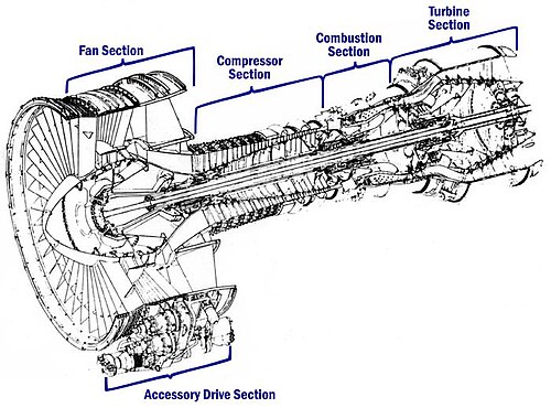 CF6 struts linking the fan case to the compressor case transfer the air loads from the inlet to the engine backbone, causing bending, case distortion and blade tip rubs. Clearances have to be increased to prevent rubs and performance is lost.
![General Electric CF6-6 engine. Aerodynamic loads on the inlet cowl (left) are highest at high angles of attack during take-off rotation and climb. The air approaching from below[139] has to turn into the engine inlet and the force required to change its momentum is reacted as an upwards force on a CF6-50 inlet of about 4 tons.[140] The inlet is bolted to the fan case and the bending moment is transferred inwardly through the struts shown into the core casing.](https://img-server.japedia.wiki/wikipedia/commons/thumb/5/5f/General_Electric_GE_CF6-6_High-bypass_turbofan_engine_-_NARA_-_17447451_(cropped).jpg/500px-General_Electric_GE_CF6-6_High-bypass_turbofan_engine_-_NARA_-_17447451_(cropped).jpg)
-
![The Pratt & Whitney JT3D is an example of an early turbofan engine. These engines typically encountered bending along the length of the engine and localised out of roundness where the thrust was transferred from the engine. These issues caused no real concern because thrust levels which caused the distortions were low enough and blade clearances were large enough.[141]](https://img-server.japedia.wiki/wikipedia/commons/thumb/0/09/American_Airlines_C.R._Smith_Museum_May_2019_17_%28Pratt_%26_Whitney_JT3D%29.jpg/500px-American_Airlines_C.R._Smith_Museum_May_2019_17_%28Pratt_%26_Whitney_JT3D%29.jpg) The Pratt & Whitney JT3D is an example of an early turbofan engine. These engines typically encountered bending along the length of the engine and localised out of roundness where the thrust was transferred from the engine. These issues caused no real concern because thrust levels which caused the distortions were low enough and blade clearances were large enough.[141]
The Pratt & Whitney JT3D is an example of an early turbofan engine. These engines typically encountered bending along the length of the engine and localised out of roundness where the thrust was transferred from the engine. These issues caused no real concern because thrust levels which caused the distortions were low enough and blade clearances were large enough.[141] -
![A Pratt & Whitney JT9D museum exhibit with none of the accessories, tubes, wiring and cowls which cover a functional engine. Revealed are the casings bolted together which make up the structural backbone of the engine.[142] The engine thrust is transferred to the aircraft pylon at the top of the turbine case. As this is above the engine centerline where the thrust acts it causes backbone bending in the core engine[143] which in turn causes causes blade tip rubs and performance loss.](https://img-server.japedia.wiki/wikipedia/commons/thumb/1/1a/JT9D_on_747.JPG/500px-JT9D_on_747.JPG) A Pratt & Whitney JT9D museum exhibit with none of the accessories, tubes, wiring and cowls which cover a functional engine. Revealed are the casings bolted together which make up the structural backbone of the engine.[142] The engine thrust is transferred to the aircraft pylon at the top of the turbine case. As this is above the engine centerline where the thrust acts it causes backbone bending in the core engine[143] which in turn causes causes blade tip rubs and performance loss.
A Pratt & Whitney JT9D museum exhibit with none of the accessories, tubes, wiring and cowls which cover a functional engine. Revealed are the casings bolted together which make up the structural backbone of the engine.[142] The engine thrust is transferred to the aircraft pylon at the top of the turbine case. As this is above the engine centerline where the thrust acts it causes backbone bending in the core engine[143] which in turn causes causes blade tip rubs and performance loss. -
![General Electric GE90 shows one of two locations (45 degrees either side of top centre) on fan frame where engine thrust is transferred by links to the rear thrust mount for transfer to the aircraft pylon.[136]](https://img-server.japedia.wiki/wikipedia/commons/thumb/a/aa/2016.10.13.111932_Detail_GE90_jet_engine_Future_of_Flight_Center_%26_Boeing_Tour_Everett_Washington.jpg/500px-2016.10.13.111932_Detail_GE90_jet_engine_Future_of_Flight_Center_%26_Boeing_Tour_Everett_Washington.jpg) General Electric GE90 shows one of two locations (45 degrees either side of top centre) on fan frame where engine thrust is transferred by links to the rear thrust mount for transfer to the aircraft pylon.[136]
General Electric GE90 shows one of two locations (45 degrees either side of top centre) on fan frame where engine thrust is transferred by links to the rear thrust mount for transfer to the aircraft pylon.[136] -
 GE90 shows one of two thrust links to the rear thrust mount on the exhaust case. Early JT9D and CF6 engines had thrust transferred from a single location on the top of the engine backbone which distorted the casing requiring increased tip clearances to prevent rubs. Acceptable distortion, with smaller tip clearances, was obtained if thrust was shared between 2 locations, one either side of vertical. This is common on modern engines of this type.
 -
 Trent 900 thrust loads are transferred from the engine through 2 thrust links (shown with orange maintenance protective sleeves) connected to the engine rear mount and wing pylon.
![The Pratt & Whitney JT3D is an example of an early turbofan engine. These engines typically encountered bending along the length of the engine and localised out of roundness where the thrust was transferred from the engine. These issues caused no real concern because thrust levels which caused the distortions were low enough and blade clearances were large enough.[141]](https://img-server.japedia.wiki/wikipedia/commons/thumb/0/09/American_Airlines_C.R._Smith_Museum_May_2019_17_(Pratt_&_Whitney_JT3D).jpg/500px-American_Airlines_C.R._Smith_Museum_May_2019_17_(Pratt_&_Whitney_JT3D).jpg)
![General Electric GE90 shows one of two locations (45 degrees either side of top centre) on fan frame where engine thrust is transferred by links to the rear thrust mount for transfer to the aircraft pylon.[136]](https://img-server.japedia.wiki/wikipedia/commons/thumb/a/aa/2016.10.13.111932_Detail_GE90_jet_engine_Future_of_Flight_Center_&_Boeing_Tour_Everett_Washington.jpg/500px-2016.10.13.111932_Detail_GE90_jet_engine_Future_of_Flight_Center_&_Boeing_Tour_Everett_Washington.jpg)
Internal or secondary air system
The use of air for internal systems increases fuel consumption so there is a need to minimize the airflow required. The internal air system uses secondary air for cooling, keeping oil in bearing chambers, to control bearing thrust load for bearing life, and preventing hot gas ingestion from turbine gas flow into disc cavities. It is a cooling system which uses airflow to transfer heat away from hot parts and maintain them at a temperature which ensures the life of parts such as turbine discs and blades. It is also a purge system which uses air to pressurize cavities to prevent hot flowpath gas from entering and overheating disc rims where blades are attached. It is used to cool or heat parts to control radial clearances (clearance control system). Early radial compressor engines used supplementary means for cooling air, for example a dedicated impeller or a fan machined integral with the turbine disc. The air sources for axial engines are different stages along the compressor depending on the different air system pressure requirements. Use of a single stage impeller as the last high pressure stage on small turbofan engines gives the flexibility of three different source pressures from the single stage, impeller entry, halfway through the stage (impeller tip) and diffuser exit (at combustor pressure). The air system sinks are the primary gas path where turbine cooling air is returned, for example, and the oil system vent overboard.
-
 Pratt & Whitney J42 shows secondary air system impeller for bearing cooling air.
 -
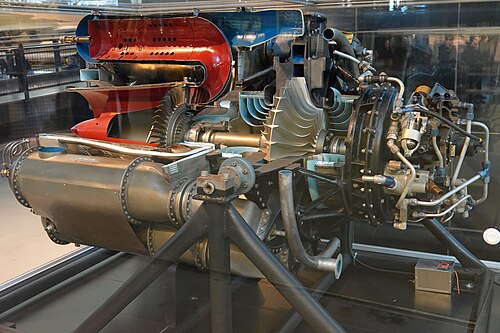 General Electric J31 secondary air fan blades integral with turbine disc for disc cooling.
 -
de Havilland Ghost shows labyrinth teeth on the impeller backface to reduce air loss from the impeller and control the pressure on the back face. The radial position of the seal is chosen to set the area on which the pressure acts so the forward thrust on the impeller substantially balances the rearward thrust from the turbine which reduces the axial force on the rotor thrust bearing.[144]
-
Rolls-Royce Turbomeca Adour labyrinth seals with honeycomb shrouds on turbine discs. The one visible to the left reduces leakage between the two turbine stages. The one visible to the right reduces leaks from the combustor high pressure gas needed by the turbine.
-
![Adour labyrinth seal with 3 fins on the blade platforms and a honeycomb shroud is a type of rim seal to prevent hot gas ingestion at the turbine disc rim.[145]](https://img-server.japedia.wiki/wikipedia/commons/thumb/7/7e/Turbine_of_a_sectioned_Rolls-Royce_Turbom%C3%A9ca_Adour_turbofan.jpg/500px-Turbine_of_a_sectioned_Rolls-Royce_Turbom%C3%A9ca_Adour_turbofan.jpg) Adour labyrinth seal with 3 fins on the blade platforms and a honeycomb shroud is a type of rim seal to prevent hot gas ingestion at the turbine disc rim.[145]
Adour labyrinth seal with 3 fins on the blade platforms and a honeycomb shroud is a type of rim seal to prevent hot gas ingestion at the turbine disc rim.[145] -
![CFM56 showing internal air system overboard vent for the oil system (vent tube in the exhaust). Secondary air enters the bearing compartments through labyrinth seals to prevent oil escaping in the opposite direction. The air continually escapes from the system through the vent with some oil mist after passing through a centrifugal air/oil separator.[146]](https://img-server.japedia.wiki/wikipedia/commons/thumb/e/e3/CFM_International_CFM56-7B26_fitted_to_Qantas_%28VH-VZY%29_Boeing_737-838_%28WL%29_at_the_Canberra_Airport_open_day.jpg/500px-CFM_International_CFM56-7B26_fitted_to_Qantas_%28VH-VZY%29_Boeing_737-838_%28WL%29_at_the_Canberra_Airport_open_day.jpg) CFM56 showing internal air system overboard vent for the oil system (vent tube in the exhaust). Secondary air enters the bearing compartments through labyrinth seals to prevent oil escaping in the opposite direction. The air continually escapes from the system through the vent with some oil mist after passing through a centrifugal air/oil separator.[146]
CFM56 showing internal air system overboard vent for the oil system (vent tube in the exhaust). Secondary air enters the bearing compartments through labyrinth seals to prevent oil escaping in the opposite direction. The air continually escapes from the system through the vent with some oil mist after passing through a centrifugal air/oil separator.[146]

![CFM56 showing internal air system overboard vent for the oil system (vent tube in the exhaust). Secondary air enters the bearing compartments through labyrinth seals to prevent oil escaping in the opposite direction. The air continually escapes from the system through the vent with some oil mist after passing through a centrifugal air/oil separator.[146]](https://img-server.japedia.wiki/wikipedia/commons/thumb/e/e3/CFM_International_CFM56-7B26_fitted_to_Qantas_(VH-VZY)_Boeing_737-838_(WL)_at_the_Canberra_Airport_open_day.jpg/500px-CFM_International_CFM56-7B26_fitted_to_Qantas_(VH-VZY)_Boeing_737-838_(WL)_at_the_Canberra_Airport_open_day.jpg)
Performance deterioration
Gas path deterioration and increasing EGT coexist. As the gas path deteriorates the EGT limit ultimately prevents the take-off thrust from being achieved and the engine has to be repaired.[147] The engine performance deteriorates with use as parts wear, meaning the engine has to use more fuel to get the required thrust. A new engine starts with a reserve of performance which is gradually eroded. The reserve is known as its temperature margin and is seen by a pilot as the EGT margin. For a new CFM International CFM56-3 the margin is 53 °C.[148][43] Kraus[149] gives the effect on increased fuel consumption of typical component degradation during service.
-
![The Pratt & Whitney JT8D has a full length fan duct which is a rigid case construction which resists inlet air loads during aircraft rotation. Compared to the later JT9D it has relatively loose clearances between rotating and stationary parts so blade tip rubs as a source of performance deterioration were not an issue.[150]](https://img-server.japedia.wiki/wikipedia/commons/thumb/2/23/Pratt_%26_Whitney_JT8D-17A_1.JPG/500px-Pratt_%26_Whitney_JT8D-17A_1.JPG) The Pratt & Whitney JT8D has a full length fan duct which is a rigid case construction which resists inlet air loads during aircraft rotation. Compared to the later JT9D it has relatively loose clearances between rotating and stationary parts so blade tip rubs as a source of performance deterioration were not an issue.[150]
The Pratt & Whitney JT8D has a full length fan duct which is a rigid case construction which resists inlet air loads during aircraft rotation. Compared to the later JT9D it has relatively loose clearances between rotating and stationary parts so blade tip rubs as a source of performance deterioration were not an issue.[150] -
![The Pratt & Whitney JT9D with a big increase in thrust over the JT8D raised awareness how to transfer engine thrust to the aircraft without bending the engine too much and causing rubs and performance deterioration.[151]](https://img-server.japedia.wiki/wikipedia/commons/thumb/a/a7/P%26W_JT9D_cutaway.jpg/500px-P%26W_JT9D_cutaway.jpg) The Pratt & Whitney JT9D with a big increase in thrust over the JT8D raised awareness how to transfer engine thrust to the aircraft without bending the engine too much and causing rubs and performance deterioration.[151]
The Pratt & Whitney JT9D with a big increase in thrust over the JT8D raised awareness how to transfer engine thrust to the aircraft without bending the engine too much and causing rubs and performance deterioration.[151] -
 Klimov VK-1 centrifugal impeller showing that the blades have rubbed on the shroud causing increased clearance and leakage losses.
 -
Turbomeca Marboré IV engine showing location of leakage between impeller blades and stationary shroud, shown sectioned and painted blue. This is the leak path for a centrifugal impeller equivalent to an axial blade tip to casing clearance.[118] The clearance between the impeller vanes and their shroud is visible and has to be as small as possible without causing rubbing contact. This keeps leakage to a minimum and contributes to the efficiency of the engine.
-
 An example of the appearance of minor compressor blade tip rubs on their shrouds.
 -
![A used CFM56 high pressure turbine blade. New blades have 3 different-depth notches at the tip to aid visual assessment (using a borescope) of rubbed away material and consequent increase in tip clearance. 0.25 mm of lost blade-tip causes a 10 deg C loss of EGT margin.[152]](https://img-server.japedia.wiki/wikipedia/commons/thumb/a/a1/CFM56_High_Pressure_Turbine_Blade.JPG/500px-CFM56_High_Pressure_Turbine_Blade.JPG) A used CFM56 high pressure turbine blade. New blades have 3 different-depth notches at the tip to aid visual assessment (using a borescope) of rubbed away material and consequent increase in tip clearance. 0.25 mm of lost blade-tip causes a 10 deg C loss of EGT margin.[152]
A used CFM56 high pressure turbine blade. New blades have 3 different-depth notches at the tip to aid visual assessment (using a borescope) of rubbed away material and consequent increase in tip clearance. 0.25 mm of lost blade-tip causes a 10 deg C loss of EGT margin.[152] -
![CFM56 turbine nozzle guide vanes. The area for the combustor gas flow for the complete ring of vanes at the narrowest part of the passage is known as the turbine area. When the vane trailing edges deteriorate the area increases and the engine runs hotter, which causes increasingly rapid deterioration, and uses more fuel to reach take-off thrust.[153]](https://img-server.japedia.wiki/wikipedia/commons/thumb/b/b7/CFM56_High_Pressure_Turbine_Vane.JPG/500px-CFM56_High_Pressure_Turbine_Vane.JPG) CFM56 turbine nozzle guide vanes. The area for the combustor gas flow for the complete ring of vanes at the narrowest part of the passage is known as the turbine area. When the vane trailing edges deteriorate the area increases and the engine runs hotter, which causes increasingly rapid deterioration, and uses more fuel to reach take-off thrust.[153]
CFM56 turbine nozzle guide vanes. The area for the combustor gas flow for the complete ring of vanes at the narrowest part of the passage is known as the turbine area. When the vane trailing edges deteriorate the area increases and the engine runs hotter, which causes increasingly rapid deterioration, and uses more fuel to reach take-off thrust.[153] -
 A V2500 vane showing thermal damage at the trailing edge which causes performance loss by altering the flow area.
 -
![The rough turbine blade airfoil surfaces have a higher friction coefficient than smooth surfaces and cause friction drag which is a source of loss in the turbine.[154]](https://img-server.japedia.wiki/wikipedia/commons/thumb/3/38/TURBINE_BLADES_-_DPLA_-_df5b1b1c388e127aca37fc549964a38c.jpg/500px-TURBINE_BLADES_-_DPLA_-_df5b1b1c388e127aca37fc549964a38c.jpg) The rough turbine blade airfoil surfaces have a higher friction coefficient than smooth surfaces and cause friction drag which is a source of loss in the turbine.[154]
The rough turbine blade airfoil surfaces have a higher friction coefficient than smooth surfaces and cause friction drag which is a source of loss in the turbine.[154]
![The Pratt & Whitney JT9D with a big increase in thrust over the JT8D raised awareness how to transfer engine thrust to the aircraft without bending the engine too much and causing rubs and performance deterioration.[151]](https://img-server.japedia.wiki/wikipedia/commons/thumb/a/a7/P&W_JT9D_cutaway.jpg/500px-P&W_JT9D_cutaway.jpg)
.jpg/500px-Repair_process_for_a_V2500_high-pressure_turbine_guide_vane_(1).jpg)
American Airlines experience with the JT3C turbojet included cracking and bowing of the turbine nozzle guide vanes which adversely affected the gas flow to the rotating turbine blades causing increased fuel consumption. More significant was erosion of turbine parts by hard carbon lumps which formed around the fuel nozzles and periodically breaking away and striking and eroding turbine blades and nozzle guide vanes causing loss of EGT margin.[155]
Prior to the doubling and tripling price of fuel in the early 1970s the regain of performance after deterioration was largely a by-product of maintaining engine reliability. The rising cost of fuel and a new awareness on conservation of energy led to a need to understand which type and amount of component degradation caused how much of an increase in fuel consumption.[156] Higher bypass ratio engines were shown to be more susceptible to structural deformations which caused blade tip and seal clearances to be opened up by rubs.
American Airlines conducted tests on early bypass engines to understand to what degree component wear and accumulation of atmospheric dirt affected fuel consumption. Gas path surfaces in the fan and compressor were found to be coated with deposits of dirt, salt and oil which increased surface roughness and caused performance loss.[157] A compressor wash on a particular Pratt & Whitney JT8D bypass engine reduced the fuel consumption by 110 pounds of fuel for every hour run.[158]
Clearances between rotating and stationary parts are required to prevent contact. Increasing clearances, which occur in service as a result of rubbing, reduce the thermal efficiency which shows up when the engine uses more fuel than before. An American Airlines test on a Pratt & Whitney JT3D engine found that increasing the HP turbine tip clearance by 0.031 inch caused a 0.9% increase in fuel used.[159]
The advent of the high bypass engines introduced new structural requirements necessary to prevent blade rubs and performance deterioration. Prior to this the JT8D, for example, had thrust bending deflections minimized with a long stiff one-piece fan duct which isolated the internal engine cases from aerodynamic loads. The JT8D had good performance retention with its moderate turbine temperature and stiff structure. Rigid case construction installed engine not adversely affected by axial bending loads from inlet on TO rotation. The engine had relatively large clearances between rotating and stationary components so compressor and turbine blade tip rubs were not significant and performance degradation came from distress to the hot section and compressor blade increasing roughness and erosion.[160]
Emissions
The connection between emissions and fuel consumption is the combustion inefficiency which wastes fuel. Fuel should be completely burned so all chemical energy is liberated as heat.[161] The formation of pollutants signifies that fuel has been wasted and more fuel is required to produce a particular thrust than would otherwise be.
Noise
Noise influences the social acceptability of aircraft and maximum levels measured during takeoff and approach flyover are legislated around airports. Military aircraft noise is the subject of complaints from people living near military airfields and in remote areas under the flight paths of low level training routes. Prior to the introduction into service of the first jet airliners noise was already the subject of citizen actions around airports due to unacceptable noise from the last generation of piston-engined airliners such as xxx. Forewarned early operators of jet airliners introduced their services with noise abatement takeoff procedures, Comet Caravelle,
Passenger cabin and cockpit noise in civil aircraft and cockpit noise in military aircraft has a contribution from jet engines both as engine noise and structure-borne noise originating from engine rotor out of balance.
Starting time
Starting time is the time taken from initiating the starting sequence to reaching idle speed. A CFM-56 typical start time is 45–60 seconds.[162] Starting time is a flight safety issue for airstarts because starting has to be completed before too much altitude has been lost.[163]
Weight
The weight of an engine is reflected in the weight of the aircraft and introduces some drag penalty. Extra engine weight means a heavier structure and reduces aircraft payload.[164]
Size
The size of an engine has to be established within the engine installation envelope agreed during the design of the aircraft. The thrust governs the flow area hence size of the engine. A criterion of pounds of thrust per square foot of compressor inlet is a figure of merit. The first operational turbojets in Germany had axial compressors to meet a 1939 request from the German Air Ministry to develop engines producing 410 lb/sq ft.[165]
Cost
A lower fuel consumption engine reduces airline expenditure on buying fuel for a given fuel cost. Deterioration of performance(increased fuel consumption) in service has a cumulative effect on fuel costs as the deterioration and rise in consumption is progressive. The cost of parts replacement has to be considered relative to the saving in fuel.[166]
Terminology and explanatory notes
Clarifying momentum, work, energy, power
A basic explanation for the way burning fuel results in engine thrust uses terminology like momentum, work, energy, power and rate. Correct use of the terminology may be confirmed by using the idea of fundamental units which are mass M, length L and time T, together with the idea of a dimension, i.e. power, of the fundamental unit, say L1 for distance, and in a derived unit, say speed which is distance over time, with dimensions L1 T −1[167] The object of the jet engine is to produce thrust which it does by increasing the momentum of the air passing through it. But thrust isn't caused by the change in momentum. It's caused by the rate of change in momentum. So thrust, which is a force, has to have the same dimensions as rate of change of momentum, not momentum. Efficiences may be expressed as ratios of energy rate or power which has the same dimensions.
Force dimensions are M1 L1 T−2 , momentum has dimensions M1L1 T−1 and rate of change of momentum has dimensions M1 L1T−2, ie the same as force. Work and energy are similar quantities with dimensions M1 L2T−2. Power has dimensions M1 L2T−3.[168]
References
- ^ Gas Turbine Performance, Second Edition, Walsh and Fletcher 2004, ISBN 0 632 06434-X, Preface
- ^ "EGT margin indicates engine health"' pp. 5–11, Safety first The Airbus Safety magazine, February 2022
- ^ a b "A Variable Cycle Engine for Subsonic Transport Applications - PDF Free Download". docplayer.net. Retrieved 2023-11-16.
- ^ https://arc.aiaa.org/doi/abs/10.2514/1.9176?journalCode=jpp,"Ideas and Methods of Turbomachinery Aerodynamics: A Historical View", Cumpsty and Greitzer, Fig. 1
- ^ An engine applies a thrust force to a stationary aircraft and thrust work is done on the aircraft when it moves under the influence.
- ^ a b Kurzke, Joachim; Halliwell, Ian (2018). "Propulsion and Power". SpringerLink. doi:10.1007/978-3-319-75979-1. ISBN 978-3-319-75977-7.
- ^ Hawthorne, William (1978). "Aircraft propulsion from the back room". The Aeronautical Journal. 82 (807): 93–108. doi:10.1017/S0001924000090424. ISSN 0001-9240. S2CID 117522849.
- ^ Gaffin, William O.; Lewis, John H. (1968). "Development of the High Bypass Turbofan". Annals of the New York Academy of Sciences. 154 (2): 576–589. Bibcode:1968NYASA.154..576G. doi:10.1111/j.1749-6632.1968.tb15216.x. ISSN 0077-8923. S2CID 84722218.
- ^ The Aerothermodynamics of Aircraft Gas Turbine Engines, Oates, Editor, AFAPL-TR-78-=52, WP AFB, Ohio, pp. 1–41
- ^ AGARD (Advisory Group for Aerospace Research and Development), Lecture Series No.136: Ramjet and Ramrocket Propulsion Systems for Missiles.
- ^ a b "Some Fundamental Aspects of Ramjet Propulsion". ARS Journal. Vol. 27, no. 4. American Institute of Aeronautics. April 1957 – via Internet Archive.
- ^ "Supersonic Stovepipes". The Cornell Engineer. Vol. 16, no. 6. Cornell University. March 1951. p. 9 – via Internet Archive.
- ^ "Gas Turbines And Their Problems", Hayne Constant, Todd Reference Library, Todd Publishing Group Ltd., 1948, p. 46
- ^ Kiran Siddappaji (November 2008). Benefits of GE 90 representative turbofan through cycle analysis (Report). doi:10.13140/RG.2.2.25078.50243.
- ^ Henning Struchtrup; Gwynn Elfring (June 2008). "External losses in high-bypass turbo fan air engines". International Journal of Exergy. 5 (4): 400. doi:10.1504/IJEX.2008.019112.
- ^ a b Rubert, Kennedy F. (1945-02-01). An analysis of jet-propulsion systems making direct use of the working substance of a thermodynamic cycle (Report).
- ^ Smith, Trevor I.; Christensen, Warren M.; Mountcastle, Donald B.; Thompson, John R. (2015-09-23). "Identifying student difficulties with entropy, heat engines, and the Carnot cycle". Physical Review Special Topics - Physics Education Research. 11 (2): 020116. arXiv:1508.04104. Bibcode:2015PRPER..11b0116S. doi:10.1103/PhysRevSTPER.11.020116.
- ^ Transactions The Manchester Association of Engineers 1904, The Temperature-Entropy Diagram, Mr. G. James Wells, p. 237
- ^ Report of the committee appointed on the 31st March, 1896, to consider and report to the Council upon the subject of the definition of a standard or standards of thermal efficiency for steam-engines . London, the Institution. 1898.
- ^ "Gas Turbine Aero-thermodynamics", Sir Frank Whittle, ISBN 0-08-026718-1, p. 2
- ^ Cumpsty, N. A. (1997). Jet propulsion: a simple guide to the aerodynamic and thermodynamic design and performance of jet engines. Cambridge; New York: Cambridge University Press. ISBN 978-0-521-59330-4 – via Internet Archive.
- ^ Entropy Generation In Turbomachinery Flows"'Denton, SAE 902011, p. 2251
- ^ "Loss mechanisms in Turbomachines" Denton, ASME 93-GT-435, p. 4
- ^ "Jet engine | Engineering, Design, & Functionality | Britannica". Britannica. 2023-10-24. Retrieved 2023-11-16.
- ^ Journal of Aircraft September-October 1966: Vol 3 Iss 5. American Institute of Aeronautics and Astronautics. September 1966 – via Internet Archive.
- ^ 'Jet Propulsion For Airplanes', Buckingham, NACA report 159, p. 85
- ^ Zhemchuzhin, N. A.; Levin, M. A.; Merkulov, I. A.; Naumov, V. I.; Pozhidayev, O. A.; Frolov, S. P.; Frolov, V. S. (1977-01-01). Soviet aircraft and rockets. NASA.
- ^ a b Lewis, John Hiram (1976). "Propulsive efficiency from an energy utilization standpoint". Journal of Aircraft. 13 (4): 299–302. doi:10.2514/3.44525. ISSN 0021-8669.
- ^ rayner joel (1960). heat engines. Internet Archive.
- ^ Weber, Richard J.; Mackay, John S. (1958-09-01). An Analysis of Ramjet Engines Using Supersonic Combustion (Report).
- ^ a b Mattingly, Jack D.; Boyer, Keith M. (2016-01-20). Elements of Propulsion: Gas Turbines and Rockets, Second Edition. Reston, VA: American Institute of Aeronautics and Astronautics, Inc. doi:10.2514/4.103711. ISBN 978-1-62410-371-1.
- ^ Smith G. Geoffrey (1946). Gas Turbines And Jet Propulsion For Aircraft.
- ^ Theory of Jet Engines (Report).
- ^ "Performance and Ranges of Application of Various Types of Aircraft-Propulsion System". UNT Digital Library. August 1947. Retrieved 2023-11-16.
- ^ "Design of Tail Pipes for Jet Engines-Including Reheat", Edwards, The Aeronautical Journal, Volume 54, Issue 472, Fig. 1.
- ^ "Engine Technology Development to Address Local Air Quality Concerns", Moran, ICAO Colloquium on Aviation Emissions with Exhibition, 14–16 May 2007
- ^ https://arc.aiaa.org/doi/abs/10.2514/3.44525?journalCode=ja "Propulsive Efficiency from an Energy Utilization Standpoint", Lewis, Fig. 2
- ^ "Rolls-Royce's Pearl 10X Set for 747 Flying Testbed Evaluation | Aviation Week Network".
- ^ On the design of energy efficient aero engines, Richard Avellan, 2011, ISBN 978-91-7385-564-8, Figure 6
- ^ "Jet engine | Engineering, Design, & Functionality | Britannica". 6 December 2023.
- ^ https://ntrs.nasa.gov/citations/19930082605, NACA TN 1927 Generalization of Turbojet engine performance in terms of pumping characteristics
- ^ Jet Engines And Propulsion Systems For Engineers, edited by Thaddeus Fowler, GE Aircraft Engines 1989, pp. 11–19
- ^ a b Performance of the Jet Transport Airplane, Young 2018, ISBN 978-1-118-53477-9, Fig 8.19
- ^ "American Airlines Experience with Turbojet/Turbofan Engines", Whatley, ASME 62-GTP-16
- ^ "Special Report: Air Florida Flight 90". AirDisaster.Com. Archived from the original on June 12, 2015. Retrieved May 30, 2015., p. 80
- ^ Who needs engine monitoring?, Aircraft Engine Diagnostics, NASA CP2190, 1981, p. 214
- ^ Jet Propulsion, Nicholas Cumpsty, ISBN 0 521 59674 2, p. 40
- ^ Novel Aerodynamic Loss Analysis Technique Based On CFD Predictions Of Entropy Production, Sullivan, SAE 951430, p. 343
- ^ https://arc.aiaa.org/doi/10.2514/3.43978 "Theory and Test of Flow Mixing of Turbofan Engines", Hartmann,Journal of Aircraft, Vol. 5, No. 6, Introduction
- ^ https://arc.aiaa.org/doi/abs/10.2514/6.1964-243, On The Thermodynamic Spectrum Of Airbreathing Propulsion, Builder, p.2
- ^ 'The Road To The 707', ISBN 0-9629605-0-0, p. 204
- ^ https://journals.sagepub.com/doi/10.1243/PIME_PROC_1950_163_022_02, 'The Gas Turbine in Perspective', Hayne Constant, Fig. 3, 8, 9, 10
- ^ https://patents.google.com/patent/US3357176A/en, 'Twin Spool Gas Turbine Engine with Axial and Centrifugal Compressors, column 1, lines 46–50
- ^ "Design And Development Of The Garrett F109 Turbofan Engine", Krieger et al., Canadian Aeronautics and Space Journal, Vol. 34, No. 3, September 1988 9.171
- ^ a b https://drs.faa.gov/browse/excelExternalWindow/DRSDOCID114483736420230203181002.0001?modalOpened=true,"Type Certificate Data Sheet E00095EN"
- ^ https://archive.org/details/Aviation_Week_1952-10-20, p. 13 'Split Compressors Usher in New Jet Era'
- ^ 'The Engines of Pratt & Whitney: A Technical History', ISBN 978-1-60086-711-8, p. 232
- ^ Jet Propulsion For Aerospace Applications, Second Edition, Hesse and Mumford, Library of Congress Catalog Card Number 64-18757, p. 185
- ^ https://archive.org/details/aircraftpropulsion2ed_201907, "Aircraft Propulsion", Farokhi Second Edition 2014, p. 638
- ^ NASA Conference on Engine Stall and Surge, Paper IV, NASA TM-X-67600, Fig.16-19
- ^ Flight International, 16 December 1955, p. 901
- ^ https://www.enginehistory.org/Convention/2013/SR-71Propul/SR-71Propul.shtml, cutaway J58 internal detail and J58 external detail
- ^ https://www.roadrunnersinternationale.com/pw_tales.htm p.4
- ^ Lundquist, W. G.; Cole, R. W. (1946). "BMW-003 TURBO-JET ENGINE Compared with the JUMO 004". SAE Transactions. 54: 503–510 [506]. JSTOR 44548294.
- ^ https://engineering.purdue.edu/~propulsi/propulsion/jets/tprops/pw200.html, PW206 8:1
- ^ "The Jet Engine", Rolls-Royce Limited, Publication Ref. T.S.D. 1302, July 1969, 3rd Edition, Figure 3-6 'Airflow at entry to diffuser'
- ^ https://patents.google.com/patent/US3420435,"Diffuser Construction"
- ^ https://asmedigitalcollection.asme.org/GT/proceedings/GT1972/79818/V001T01A053/231014,"A Comparison Of The Predicted And Measured Performance Of High Pressure Ratio Centrifugal Compressor Diffusers", Kenney, p. 19
- ^ https://archive.org/details/DTIC_ADA059784/page/n45/mode/2up,"All compression in engines requires a diffusion process", section 1.4.2.3
- ^ Supersonic flow is slowed in a converging duct as shown from the inlet lip to the shock trap bleed.

- ^ https://ntrs.nasa.gov/citations/19650013744,"Aerodynamic Design of Axial-Flow Compressors", p. 126
- ^ https://www.sae.org/publications/technical-papers/content/861837/, "Low Aspect Ratio Axial Flow Compressors: Why and What It Means", Wennerstrom, p. 11
- ^ https://www.worldcat.org/title/history-of-the-rolls-royce-rb211-turbofan-engine/oclc/909128142 [bare URL]
- ^ https://asmedigitalcollection.asme.org/GT/proceedings/IGT1985/79429/V001T01A006/259190,"Development of a New Technology Small Fan Jet Engine", Boyd, ASME 85-IGT-139, p. 2
- ^ https://asmedigitalcollection.asme.org/GT/proceedings/GT1969/79832/V001T01A088/231986, "An Introduction to the JT15D Engine"
- ^ https://arc.aiaa.org/doi/abs/10.2514/1.9176?journalCode=jpp,"Ideas and Methods of Turbomachinery Aerodynamics: A Historical View", Cumpsty and Greitzer, Figure 1
- ^ https://journals.sagepub.com/doi/10.1243/0954406991522680, "Axial Compressor Design", Gallimore, p. 439
- ^ https://asmedigitalcollection.asme.org/turbomachinery/article-abstract/111/4/357/419178/Low-Aspect-Ratio-Axial-Flow-Compressors-Why-and?redirectedFrom=fulltext, "Low Aspect Ratio Axial Flow Compressors: Why and What It Means", Wennerstrom, SAE 861837, p. 6
- ^ Amoo, Leye M. (2013). "On the design and structural analysis of jet engine fan blade structures". Progress in Aerospace Sciences. 60: 1–11. Bibcode:2013PrAeS..60....1A. doi:10.1016/j.paerosci.2012.08.002.
- ^ https://asmedigitalcollection.asme.org/GT/proceedings/GT1988/79191/V002T02A017/236878,"Developing The Rolls-Royce Tay", Wilson, 88-GT-302
- ^ The Impact Of Three-Dimensional Analysis On Fan Design, Clemmons et al., ASME 83-GT-136
- ^ https://patents.google.com/patent/US6071077A/en, "Swept Fan Blade"
- ^ "Modern Advances in Fan and Compressor Design using CFD", Balin, University of Colorado, Boulder, Colo. 80309
- ^ McKinney, Randal; Cheung, Albert; Sowa, William; Sepulveda, Domingo (2007). "The Pratt & Whitney TALON X Low Emissions Combustor: Revolutionary Results with Evolutionary Technology". 45th AIAA Aerospace Sciences Meeting and Exhibit. doi:10.2514/6.2007-386. ISBN 978-1-62410-012-3.
- ^ Liu, Yize; Sun, Xiaoxiao; Sethi, Vishal; Nalianda, Devaiah; Li, Yi-Guang; Wang, Lu (2017). "Review of modern low emissions combustion technologies for aero gas turbine engines". Progress in Aerospace Sciences. 94: 15. Bibcode:2017PrAeS..94...12L. doi:10.1016/j.paerosci.2017.08.001. hdl:1826/12499.
- ^ "Engine Technology Development to Address Local Air Quality Concerns", Moran, ICAO Colloquium on Aviation Emissions with Exhibition, 14-16 May 2007
- ^ "Jet Propulsion Progress", Neville and Silsbee, First Edition, McGraw-Hill Book Company, Inc., 1948, p. 127
- ^ "Series II Goblin", Flight magazine,21st February,1946
- ^ https://archive.org/details/in.ernet.dli.2015.19428/page/n71/mode/2up,"Gas Turbines and Jet Propulsion" 4th edition, Smith, Fig. 73 and 77
- ^ "Westinghouse J46 Axial Turbojet Family. Development History And Technical Profiles", Paul J. Christiansen, ISBN 978-0-692-76488-6, Figure 3 and 8
- ^ https://asmedigitalcollection.asme.org/gasturbinespower/article/132/11/116501/464800/GAS-TURBINE-COMBUSTION-Alternative-Fuels-and, p. 237
- ^ "Two-spool Turbo Wasp", Flight magazine, 27 November 1953.
- ^ "Gas Turbine Combustion" Third Edition, Lefebvre and Ballal, ISBN 978 1 4200 8605 8, pp. 15–16, Figure 1.16
- ^ https://patents.google.com/patent/US20150059355A1/en,"Method And System For Controlling Gas Turbine Performance With A Variable Backflow Margin"
- ^ http://www.netl.doe.gov>gas.turbine.handbook,"4.2.1 Cooling Design Analysis, p. 304
- ^ "Exhaust Reheat for Turbojets - A Survey of Five Years' Development Work - Part 1", Flight magazine, 8 September 1949
- ^ https://archive.org/details/DTIC_ADA361702,"Design Principles And Methods For Aircraft Gas Turbine Engines", RTO-MP-8, p. 19-5
- ^ Kurzke, Joachim; Halliwell, Ian (2018). Propulsion and Power. pp. 544–545. doi:10.1007/978-3-319-75979-1. ISBN 978-3-319-75977-7.
- ^ Kurzke, Joachim; Halliwell, Ian (2018). Propulsion and Power. p. 545. doi:10.1007/978-3-319-75979-1. ISBN 978-3-319-75977-7.
- ^ "Fast Jets-the history of reheat development at Derby", Cyril Elliott, Rolls-Royce Heritage Trust, Technical Series No 5, ISBN 1 872922 20 1, p. 116
- ^ "A Review Of Supersonic Air Intake Problems, Wyatt", Agardograph No. 27, p. 22
- ^ The First James Clayton Lecture,"The Early History Of The Whittle Jet Propulsion Gas Turbine", Air Commodore F. Whittle, p. 430 Fig. 20
- ^ Not Much Of An Engineer, Sir Stanley Hooker An Autobiography, ISBN 1 85310 285 7, p. 90
- ^ https://patents.google.com/patent/US3477455A/en,"Supersonic inlet for jet engines"
- ^ https://ntrs.nasa.gov/citations/19930090035,"Use of Shock-trap Bleed to Improve Pressure Recovery...",
- ^ https://www.semanticscholar.org/paper/Ramjet-Intakes-Cain/96dc23a101c094f19d185f7497755c0cb0d19ec8, "Ramjet Intakes", Cain, Figure 19
- ^ "Fluid-dynamic Drag", Hoerner 1965, Library of Congress Catalog Card Number 64-19666, Chapter 5 Drag of surface imperfections, p. 5-1
- ^ https://www.hindawi.com/journals/ijae/2022/3637181/, Analysis of Entropy Generation and Potential Inhibition in an Aeroengine System Environment, Liu et al., Introduction
- ^ https://www.cambridge.org/core/journals/aeronautical-journal/article/abs/aircraft-propulsion-from-the-back-room/771675086CDE0E766BE700CD6B3198E7 "Aircraft propulsion from the back room", Hawthorne, p. 101
- ^ "Seal Technology In Gas Turbine Engines", AGARD CP 237, pp. 1–2
- ^ Selecting a Material For Brazing Honeycomb in Turbine Engines, Sporer and Fortuna, Brazing and Soldering Today February 20014, p. 44
- ^ https://patents.google.com/patent/US2963307, "Honeycomb seal" Fig.1
- ^ https://www.yumpu.com/en/document/view/33920940/8th-israeli-symposium-on-jet-engine-and-gas-turbine, slide 'Effect of tip clearance on turbine efficiency'
- ^ Current Aerodynamic Issues For Aircraft Engines, Cumpsty, 11th Australian Fluid Mechanics Conference, University of Tasmania, 14–18 December 1992, p. 804
- ^ CFM Flight Ops Support, Performance Deterioration p. 48
- ^ AGARD CP 237 'Gas Path Sealing in Turbine Engines', Ludwig, Figure 6(a)
- ^ https://ntrs.nasa.gov/citations/19780013166 "Gaspath Sealing in Turbine Engines", Ludwig Fig. 6(d)
- ^ a b AGARD CP 237 'Gas Path Sealing in Turbine Engines', Figure 6(a)
- ^ AGARD CP 237 'Gas Path Sealing in Turbine Engines', Figure 7(b)
- ^ "Jet Engines And Propulsion Systems For Engineers, GE Aircraft Engines 1989, pp. 8–10
- ^ https://ntrs.nasa.gov/citations/20060051674 "Transient tip clearance" fig.1
- ^ https://patents.google.com/patent/US6126390A/en "Passive clearance control system for a gas turbine"
- ^ "Turbine Engine Clearance Control Systems: Current Practices and Future Directions". September 2002.
- ^ https://www.easa.europa.eu/en/document-library/product-certification-consultations/proposed-special-condition-1, EASA "Turbine Engines Transient over-temperature, over-speed and over-torque limit approval", 'When the engine characteristics are such that an acceleration from cold produces a transient over-temperature in excess of that for steady state running...'
- ^ Training Manual CFM56-5A Engine Systems, Clearance Control Chapters 75-21-00 and 75-22-00
- ^ https://arc.aiaa.org/doi/book/10.2514/4.867293 "The Engines of Pratt & Whitney:A Technical History", Connors, p. 219
- ^ https://www.enginehistory.org,"Wright's T35 Turboprop Engine, et al. by Doug Cuty, 1 Sept 2020 "... a constant outer diameter and a pressure ratio of 8:1 ... seal leakage was so bad that the constant outer diameter approach was terminated."
- ^ 'Honeycomb Seal", US patent 2,963,307
- ^ https://archive.org/stream/DTIC_ADA060293/DTIC_ADA060293_djvu.txt, "AGARD CP 237", pp. 1–9
- ^ "Jet Engine Force Frame", US patent 3,675,418
- ^ https://nyaspubs.onlinelibrary.wiley.com/doi/abs/10.1111/j.1749-6632.1968.tb15216.x, "Development Of The High Bypass Turbofan", p. 588 'Advanced Structural Concepts'
- ^ "747 Creating The World's First Jumbo Jet And Other Adventures From A Life In Aviation", Sutter, ISBN 978 0 06 088241 9, p. 187
- ^ Flight International,13 November 1969, p. 749
- ^ Koff, B. (1991). "Spanning the globe with jet propulsion". 21st Annual Meeting and Exhibit. p. 8. doi:10.2514/6.1991-2987.
- ^ https://patents.google.com/patent/US5320307A/en, "Aircraft Engine Thrust Mount", Abstract
- ^ a b https://www.freepatentsonline.com/5873547.html, "Aircraft Engine Thrust Mount", Sheet 2
- ^ https://archive.org/details/boeing-777-ian-allan-abc, "Boeing 777, Campion-Smith, p. 52
- ^ https://asmedigitalcollection.asme.org/memagazineselect/article-abstract/133/03/46/380174/Mounting-TroublesThe-First-Jumbo-Jet-was-an?redirectedFrom=fulltext, "Mounting Troubles", Langston, p. 7
- ^ https://ntrs.nasa.gov/citations/19820020420, NASA CR-165573, Figure 4-1 'Inlet angle of attack'
- ^ https://ntrs.nasa.gov/citations/19790012903,"CF6 jet engine performance improvement program. Task 1: Feasibility analysis", Fig.31
- ^ Load distributing Thrust Mount, US patent 3,844,115, column 1 line 66
- ^ Langston, Lee S. (2011). "Mounting Troubles". Mechanical Engineering. 133 (3): 46–49. doi:10.1115/1.2011-MAR-6.
- ^ https://ntrs.nasa.gov/citations/19790022018, "Energy Efficient Engine Flight Propulsion System",'Mounting System' 4.11.2.3
- ^ "Flight", February 6, 1947, "The de Havilland Ghost (DGT/50)", p. 143
- ^ "Gas path sealing in turbine engines", Ludwig, NASA TM-73890, p. 1-2, 2. Sealing locations and seal types
- ^ Training Manual CFM56-5C Engine Systems, January 2003, Published by CFMI Customer Training Center, Chapter 79-00-00 page 7
- ^ Aircraft Engine Diagnostics, NASA CP 2190, 1981, JT8D Engine Performance Retention, p. 64
- ^ https:smart cockpit.com, CFM Flight Operations Support, page 37
- ^ https://reposit.haw-hamburg.de/handle/20.500.12738/5576,"Further investigation of engine performance loss, in particular exhaust gas temperature margin, in the CF6-80C2 jet engine and recommendations for test cell modifications to record additional criteria, Tables 2.1–2.4
- ^ https://ntrs.nasa.gov/citations/19810022654,"Aircraft Engine Diagnostics", JT-8D Engine Performance Retention, p. 66
- ^ Flight International, 13 November 1969, p. 749
- ^ CFM CFM56 Series Training Manual, p. 142
- ^ Plante, Robert D. (1988). "The Nozzle Guide Vane Problem". Operations Research. 36 (1): 18–33. doi:10.1287/opre.36.1.18. JSTOR 171375.
- ^ Jet Engines And Propulsion Systems For Engineers, GE Aircraft Engines 1989, pp. 5–17
- ^ https://asmedigitalcollection.asme.org/GT/proceedings/GT1962/79931/V001T01A016/227591,"American Airlines Experience with Turbojet/Turbofan Engines", p. 4
- ^ https://ntrs.nasa.gov/citations/19750018937, p. 2
- ^ https://ntrs.nasa.gov/citations/19750018937,"Analysis of turbofan engine performance deterioration and proposed follow-on tests", p. 22
- ^ https://ntrs.nasa.gov/citations/19750018937 p.20
- ^ https://ntrs.nasa.gov/citations/19750018937, Fig.13
- ^ https://ntrs.nasa.gov/citations/19810022654,"Aircraft Engine Diagnostics", JT-8D Engine Performance Retention, p. 69
- ^ https://archive.org/details/gasturbinecombus0000lefe, Gas Turbine Combustion, Lefebvre 1983, ISBN 0 07 037029X p. 4
- ^ CFM Flight Ops Support 13 December 2005, p. 85
- ^ 「航空機、船舶、車両、発電用ガスタービンエンジンの性能予測とシミュレーション」、RTO 技術レポート TR-AVT-036、pp. 2–50
- ^ 「航空機推進」、PJマクマホン、ISBN 0 273 42324 X、58ページ
- ^ ヒルシェル、エルンスト・ハインリヒ;プレム、ホルスト。下呂市マドルン(2004)。ドイツの航空研究。 p. 226.土井:10.1007/978-3-642-18484-0。ISBN 978-3-642-62129-1。
- ^ 「航空機の進化」、ウィットフォード、ISBN 978 1 86126 870 9、p. 119
- ^ 工学熱力学の仕事と熱伝達、ロジャースとメイヒュー 1967 年、ISBN 978-0-582-44727-1、p. 15
- ^ https://archive.org/details/masslengthtime0000norm_v5r2/page/150/mode/2up、質量、長さ、時間、ノーマン・フェザー 1959 年、p. 150