
Loading article…
Quadrature amplitude modulation (QAM) is the name of a family of signal modulation methods widely used in modern telecommunications to transmit information. At its core, it conveys two independent analog signals by changing (modulating) the amplitudes of two differently phased versions of a single carrier wave using amplitude modulation. These paired analog signal channels may then be used either directly or to encode digital bit streams using joint amplitude-shift keying across the synchronized channels.
The two carrier waves are of the same frequency and are out of phase with each other by 90°, a condition known as orthogonality or quadrature. The transmitted signal is created by adding the two carrier waves together. At the receiver, the two waves can be coherently separated (demodulated) because of their orthogonality. Another key property is that the modulations are low-frequency/low-bandwidth waveforms compared to the carrier frequency, which is known as the narrowband assumption.
In M-ary transmissionamplitude-shift keying the phase is the same but with different amplitudes, while phase-shift keying (PSK) has the same amplitude but different phases. Combining these concepts leads to QAM, where both amplitude and phase are modulated, or two binary PSK signals are combined with orthogonal carriers.[1]:9,422
QAM is used extensively as a modulation scheme for digital communications systems, such as in 802.11 Wi-Fi standards. Arbitrarily high spectral efficiencies can be achieved with QAM by setting a suitable constellation size, limited only by the noise level and linearity of the communications channel.[2] QAM is being used in optical fiber systems as bit rates increase; QAM16 and QAM64 can be optically emulated with a three-path interferometer.[3][4]
In a QAM signal, one carrier lags the other by 90°, and its amplitude modulation is customarily referred to as the in-phase component, denoted by I(t). The other modulating function is the quadrature component, Q(t). So the composite waveform is mathematically modeled as:[1]:434
where fc is the carrier frequency. At the receiver, a coherent demodulator multiplies the received signal separately with both a cosine and sine signal to produce the received estimates of I(t) and Q(t). For example:
Using standard trigonometric identities, we can write this as:
Low-pass filteringr(t) removes the high frequency terms (containing 4πfct), leaving only the I(t) term. This filtered signal is unaffected by Q(t), showing that the in-phase component can be received independently of the quadrature component. Similarly, we can multiply sc(t) by a sine wave and then low-pass filter to extract Q(t).
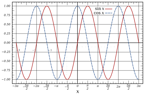
The addition of two sinusoids is a linear operation that creates no new frequency components. So the bandwidth of the composite signal is comparable to the bandwidth of the DSB (double-sideband) components. Effectively, the spectral redundancy of DSB enables a doubling of the information capacity using this technique. This comes at the expense of demodulation complexity. In particular, a DSB signal has zero-crossings at a regular frequency, which makes it easy to recover the phase of the carrier sinusoid. It is said to be self-clocking. But the sender and receiver of a quadrature-modulated signal must share a clock or otherwise send a clock signal. If the clock phases drift apart, the demodulated I and Q signals bleed into each other, yielding crosstalk. In this context, the clock signal is called a "phase reference". Clock synchronization is typically achieved by transmitting a burst subcarrier or a pilot signal. The phase reference for NTSC, for example, is included within its color burst signal.
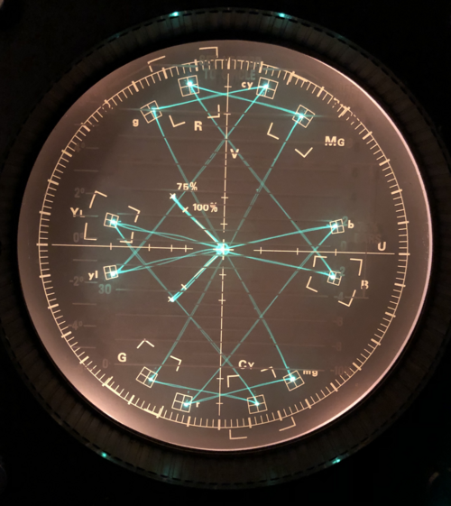
Analog QAM is used in:
Applying Euler's formula to the sinusoids in Eq.1, the positive-frequency portion of sc (or analytic representation) is:
where denotes the Fourier transform, and ︿I and ︿Q are the transforms of I(t) and Q(t). This result represents the sum of two DSB-SC signals with the same center frequency. The factor of i (= eiπ/2) represents the 90° phase shift that enables their individual demodulations.
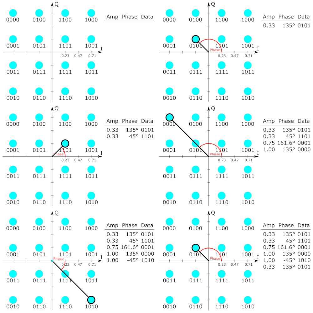

多くのデジタル変調方式と同様に、QAMにおいてもコンスタレーション図は有用です。QAMでは、コンスタレーション点は通常、垂直方向と水平方向の間隔が等しい正方形のグリッドに配置されますが、他の構成も可能です(例えば、六角形や三角形のグリッド)。デジタル通信では、データは通常バイナリであるため、グリッド内の点の数は通常2のべき乗(2、4、8、…)であり、これはシンボルあたりのビット数に対応します。最も単純で一般的に使用されるQAMコンスタレーションは、正方形に配置された点で構成されており、16-QAM、64-QAM、256-QAM(2の偶数乗)などがあります。Cross-QAMなどの非正方形コンスタレーションは、より高い効率を提供できますが、モデムの複雑さが増すコストのため、ほとんど使用されません。[ 1 ]
より高い次数コンスタレーションに移行することで、シンボルあたりより多くのビットを送信することが可能になります。しかし、公平な比較を行うためにコンスタレーションの平均エネルギーを一定に保つには、点の間隔を狭める必要があり、ノイズやその他の劣化の影響を受けやすくなります。その結果、ビット誤り率が高くなり、平均コンスタレーションエネルギーが一定の場合、高次QAMは低次QAMよりも信頼性は低いものの、より多くのデータを伝送できます。ビット誤り率を増やさずに高次QAMを使用するには、信号エネルギーを増やすか、ノイズを減らすか、あるいはその両方を行うことで、より高い信号対雑音比(SNR)を実現する必要があります。
8- PSKで得られるデータレートを超えるデータレートが必要な場合は、QAMに移行するのが一般的です。QAMは、IQ平面上の隣接する点間の距離をより均等に分散させることで、より広いデータレートを実現できるからです。ただし、QAMでは点の振幅がすべて同じではないため、復調器は位相だけでなく振幅も正しく検出する必要があるという点が複雑になります。
64-QAMと256-QAMは、デジタルケーブルテレビやケーブルモデムの用途でよく使用されます。米国では、64-QAMと256-QAMは、SCTEがANSI/SCTE 07 2013規格で標準化したデジタルケーブルの必須変調方式です( QAMチューナーを参照) 。英国では、64-QAMは地上デジタルテレビ(Freeview)に、256-QAMはFreeview-HDに使用されています。

Communication systems designed to achieve very high levels of spectral efficiency usually employ very dense QAM constellations. For example is ADSL technology for copper twisted pairs, whose constellation size goes up to 32768-QAM (in ADSL terminology this is referred to as bit-loading, or bit per tone, 32768-QAM being equivalent to 15 bits per tone).[5]
Ultra-high capacity microwave backhaul systems also use 1024-QAM.[6] With 1024-QAM vendors can obtain gigabit capacity in a single 56 MHz channel.[6]
In moving to a higher order QAM constellation (higher data rate and mode) in hostile RF/microwave QAM application environments, such as in broadcasting or telecommunications, multipath interference typically increases. There is a spreading of the spots in the constellation, decreasing the separation between adjacent states, making it difficult for the receiver to decode the signal appropriately. In other words, there is reduced noise immunity. There are several test parameter measurements which help determine an optimal QAM mode for a specific operating environment. The following three are most significant:[7]
Technologies that increase noise resistance include adaptive coding and modulation (ACM) and XPIC.[6]
{{cite web}}: CS1 maint: others (link)


![{\displaystyle {\begin{aligned}r(t)&={\tfrac {1}{2}}I(t)\left[1+\cos(4\pi f_{c}t)\right]-{\tfrac {1}{2}}Q(t)\sin(4\pi f_{c}t)\\&={\tfrac {1}{2}}I(t)+{\tfrac {1}{2}}\left[I(t)\cos(4\pi f_{c}t)-Q(t)\sin(4\pi f_{c}t)\right].\end{aligned}}}](https://wikimedia.org/api/rest_v1/media/math/render/svg/548bd6eab15dcc86dd4f607025ffee024ce0c2c8)
![{\displaystyle s_{c}(t)_{+}={\tfrac {1}{2}}e^{i2\pi f_{c}t}[I(t)+iQ(t)]\quad {\stackrel {\mathcal {F}}{\Longrightarrow }}\quad {\tfrac {1}{2}}\left[{\widehat {I\ }}(f-f_{c})+e^{i\pi /2}{\widehat {Q}}(f-f_{c})\right],}](https://wikimedia.org/api/rest_v1/media/math/render/svg/627a100c3a2b79e4267617288854c5123cb52494)
