The Hampson–Linde cycle introduced regenerative cooling, a positive-feedback cooling system.[5] The heat exchanger arrangement permits an absolute temperature difference (e.g. 0.27°C/atm J–T cooling for air) to go beyond a single stage of cooling and can reach the low temperatures required to liquefy "fixed" gases.
The Hampson–Linde cycle differs from the Siemens cycle only in the expansion step. Whereas the Siemens cycle has the gas do external work to reduce its temperature, the Hampson–Linde cycle relies solely on the Joule–Thomson effect; this has the advantage that the cold side of the cooling apparatus needs no moving parts.[1]
The cycle
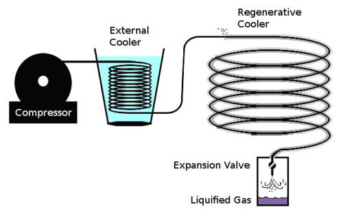
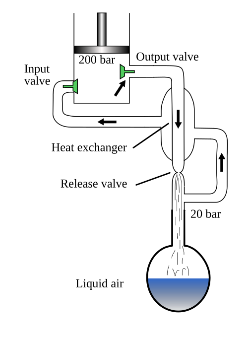
Hampson–Linde cycle sketch; this sketch does not show regeneration (gas fed back to compressor)Hampson–Linde cycle; this diagram does not include the external cooler, highlight the countercurrent heat exchanger, or show significant holdup
The cooling cycle proceeds in several steps:
The gas is compressed, which adds external energy into the gas, to give it what is needed for running through the cycle. Linde's US patent gives an example with the low side pressure of 25 standard atmospheres (370psi; 25bar) and high side pressure of 75 standard atmospheres (1,100psi; 76bar).
The high pressure gas is then cooled by immersing the gas in a cooler environment; the gas loses some of its energy (heat). Linde's patent example gives an example of brine at 10°C.
The high pressure gas is further cooled with a countercurrent heat exchanger; the cooler gas leaving the last stage cools the gas going to the last stage.
The gas is further cooled by passing the gas through a Joule–Thomson orifice (expansion valve); the gas is now at the lower pressure.
The low pressure gas is now at its coolest in the current cycle.
Some of the gas condenses and becomes output product.
The low pressure gas is directed back to the countercurrent heat exchanger to cool the warmer, incoming, high-pressure gas.